261Gx, 261Ax | IM/261Gx/Ax-EN Rev. 08 11
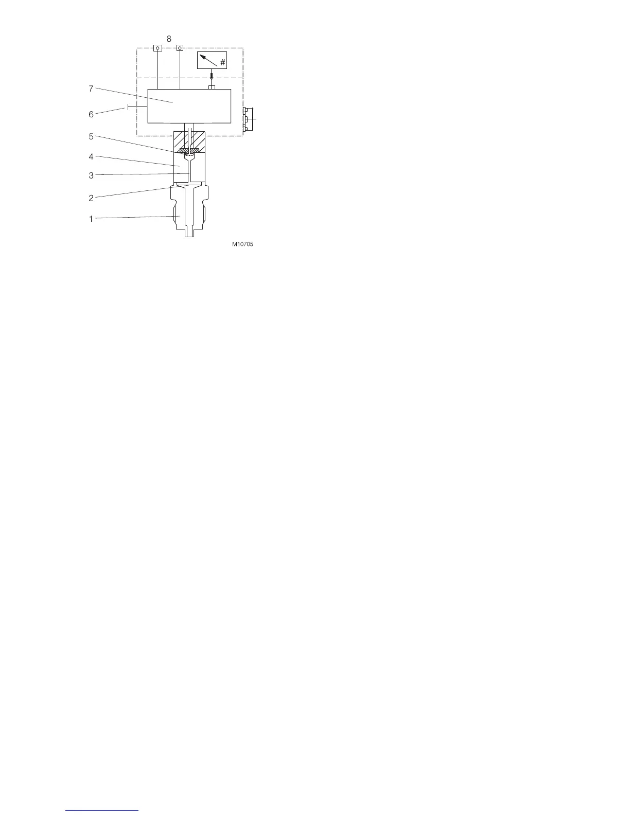
Fig. 4: 261G transmitter for pressure and level (example)
1 Process connection | 2 Separation diaphragm | 3 Filling fluid |
4 Measuring cell | 5 Pressure sensor |
6 Pushbutton for lower / upper range values |
7 Microprocessor-controlled electronics |
8 Output / Power supply
To measure the output signal and configure / calibrate the
pressure transmitter, an ampere meter must be connected
directly to the output circuit.
The lower and upper range values can be set via a pushbutton
on the electronic unit.
An optional fastener is available for attaching a stainless steel
tag so that the measuring points can be indicated.
The transmitter may also be equipped with an LCD indicator
that can be read from above (optional, can be retrofitted). With
the aid of this LCD indicator, the transmitter and its most
important functions / data can be fully configured using the
‘local’ control unit (four operating buttons on the indicator -see
‘Configuration’ chapter).

 Loading...


