Chapter 4 – ACS 504 Installation Instructions
ACS 502 Installation & Start-up Manual 4-13
current should flow from the side labeled H1 to the side labeled H2.
The wires on the CT should be connected to the grey cable on the left side of
the inverter module. The wires should be connected as follows: black - black;
white - clear. The shield is connected at the drive end, and should not be
connected at the CT end. Avoid running the signal wires parallel to the power
wires.
Note: Polarity is critical in this installation. Ensure that the WHITE lead
from the CT is connected to X1001:2 and the BLACK lead is connected
to X1001:1 on SNAT7670EFS card.
Checking the Motor
Insulation
Do not make insulation checks on the ACS 504 unless there is reason to
suspect an isolation failure. Every unit has been tested for isolation between
main circuit and chassis (2500 VAC for 1 minute) at the factory.
Before proceeding with the insulation resistance measurements, make sure
that the ACS 504 is disconnected from the input line and then disconnect the
output conductors from terminals U
2
, V
2
and W
2
.
Check that the motor cable is disconnected from the motor.
Measure the insulation resistance in the motor. The voltage range of the
insulation resistance meter must be at least equal to the input line voltage but
not exceeding 1000 V. The insulation resistance must be greater than 1 Mohm.
Measure the insulation resistance of the output conductors between the phases
and between each phase and ground. The insulation resistances must be
greater than 1 Mohm.
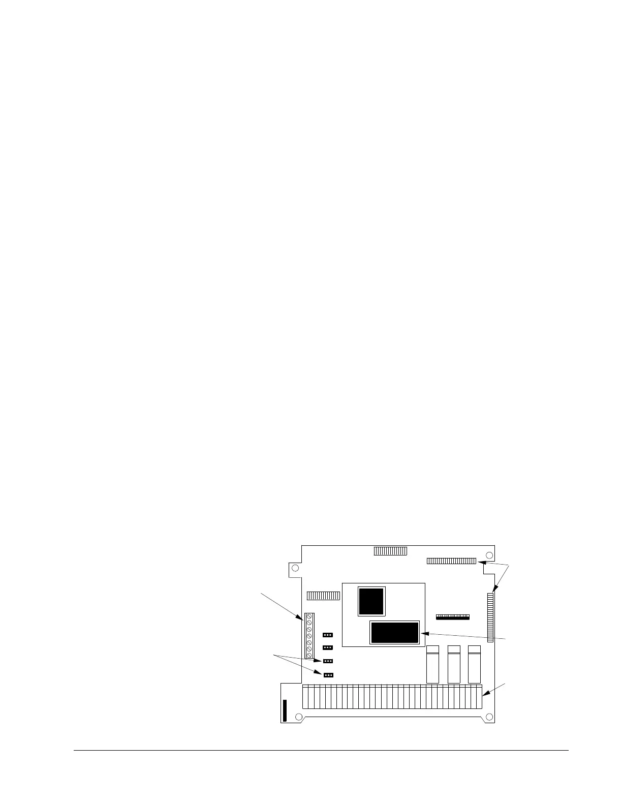
Control Connections
Available Control
Locations
The available control locations for the ACS 504 are the:
• ACS Keypad located on the front of the drive.
• X50 screw terminals on the Control Interface Card SNAT-759.
Figure 4-8 shows the control interface card SNAT-759 with terminal and
control locations.
Figure 4-9 SNAT-759 Connections
V/mA Selectors
for AI1 and AI2
X53
S1
X51
S3
noterm
X50
K1 K2 K3
X55
X54
X56
1234567891011121314151617181920 212223 242526 272829
Connectors for
Option Boards
EPROM
Customer
Interface
Terminals
S4
RS-485
Serial
Communications
S2
I
V
X57
X60
 Loading...


