ACS350 and ACS150
MUL1-R3 Installation Instructions
© 2005 ABB Oy. All Rights Reserved. 3AFE68620023 rev. B / 7.12.2005
1
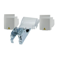
2. Fasten the gland box frame to wall with four M4 screws (not
included).
2
1. Fasten the gland box frame to drive with two M4×12 screws.
4. If control cables or fieldbus option modules will be installed,
remove the detachable lid (4) from the gland box cover.
4
WARNING! Before installing MUL1-R3
option, read the safety instructions and
mechanical and electrical installation
instructions in the drive user’s manual.
Follow the instructions when installing,
operating and servicing the drive. If
ignored, physical injury or death may
follow, or damage may occur to the
drive, motor or driven equipment.
3. If using FPBA-01 or FCAN-01 option module, remove part
from gland box frame by bending it.
3
5. With any fieldbus option module except FRSA-00, install the
option grounding plate to the gland box frame. See Mechanical
installation in the drive manual.
5