Do you have a question about the ABB ACS880-304 +A018 and is the answer not in the manual?
| Brand | ABB |
|---|---|
| Model | ACS880-304 +A018 |
| Category | Power Supply |
| Language | English |
Provides critical safety guidelines for installing, commissioning, using, and servicing the drive.
Defines the intended audience and required knowledge for using this manual.
Defines technical terms and abbreviations used throughout the manual.
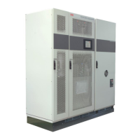
Explains the fundamental working principle of the diode supply unit and its components.
Shows the simplified main circuit diagram of the rectifier bridge, illustrating key components.
Illustrates the differences between 6-pulse and 12-pulse AC supply connections and their benefits.
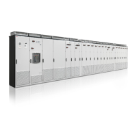
Shows a typical drive system configuration with a diode supply unit and inverter units.
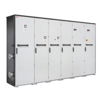
Describes the hardware features and design of the D7T and D8T supply modules.
Provides front and back layout drawings of the D7T supply module, detailing components and connections.
Details the local control devices available on the cabinet door for managing the supply unit.
Lists the functions and operation of the ACS-AP-I control panel for managing the supply unit.
Explains the information provided on the type designation label attached to the module.
Provides a detailed key for decoding the type designation, explaining basic and option codes.
Provides instructions for safely moving and lifting the transport package of the supply module.
Details the step-by-step procedure for unpacking the module from its delivery packaging.
Provides general guidelines for cabinet installation, referring to separate design and construction instructions.
Outlines the recommended solution for switching, disconnection, and protection of the ACS880-304 +A018 module.
Recommends the use of a separate auxiliary control cubicle for housing control components.
Shows an example of a cooling system for AC fuses using a thermal switch for temperature monitoring.
Explains the function of the RFI filter for improving EMC characteristics and meeting category C2 requirements.
Shows configuration examples for supply module cubicles, detailing combinations and widths.
Introduces installation examples for Rittal TS 8 enclosures and generic cabinets, detailing stages and codes.
Provides a step-by-step guide for constructing a 2×D7T, 12-pulse supply module cubicle in a Rittal TS 8 enclosure.
Details the construction stages for a 1×D8T, 6-pulse supply module cubicle in a Rittal TS 8 enclosure.
Provides construction steps for a 2×D8T, 6-pulse supply module cubicle in a Rittal TS 8 enclosure.
Details the construction stages for a 2×D8T, 12-pulse supply module cubicle in a Rittal TS 8 enclosure.
Emphasizes safety warnings for qualified electricians and ABB's liability disclaimer for installations.
Outlines essential electrical safety precautions to be followed before starting any installation work.
Provides guidance on checking the insulation of the supply unit and supply cable, and compatibility with IT systems.
Explains the process of connecting power cables and busbars, emphasizing the use of final circuit diagrams.
Provides a step-by-step procedure for making external control cable connections, emphasizing safety and grounding.
Explains how to connect auxiliary AC power to the supply module's electronics and optional components.
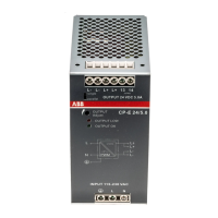
Details how to connect a 24 V DC auxiliary power supply to the BCU control unit.
Provides instructions on connecting external control cables to the supply unit, including routing and grounding.
Guides on installing optional modules onto the control unit, including wiring and configuration.
Provides initial safety precautions and instructions before commencing the installation checklist.
A comprehensive checklist to verify all installation steps have been completed correctly before start-up.
Details the step-by-step procedure for safely starting up the drive, including pre-checks and parameter settings.
Lists essential checks to perform before applying voltage, ensuring safety and correct configuration.
Outlines the procedure for safely connecting voltage to the drive's input terminals and auxiliary circuits.
Guides on setting crucial supply unit parameters, including fan options and voltage ranges.
Provides instructions and warnings for safely switching on the supply unit after all checks are complete.
Details the procedure for safely switching off the supply unit and stopping connected motors.
Provides a table for selecting the correct parameter 195.12 setting based on the unit type and frame size.
Presents a maintenance schedule with tasks and intervals for cooling fans, batteries, and other components.
Provides instructions for cleaning the interior of the cabinet and the air inlet meshes.
Details the steps for checking and replacing DC fuses on the D7T supply module, including safety warnings.
Provides instructions for checking and replacing DC fuses on the D8T supply module, including safety precautions.
Outlines the procedure for checking and replacing AC fuses, including tightening torques for different brands.
Details the procedure for replacing the cooling fan on the D7T supply module, applicable to both standard and DOL fans.
Explains how to replace the fan on the D8T supply module, including specific instructions for direct-on-line fans.
Provides a step-by-step guide for replacing the direct-on-line cooling fan on the D8T supply module.
Details the procedure for replacing the fan that cools the circuit board compartment in the D8T module.
Covers replacing cabinet cooling fans, including specific instructions for ABB air outlet kits and other fan types.
Details the procedure for cleaning the heatsink fins to ensure proper cooling and prevent overtemperature issues.
Provides a comprehensive guide for replacing the D7T supply module, including safety warnings and lifting device usage.
Details the procedure for replacing the D8T supply module, including warnings about weight and handling, and recommendations for pull-out ramps.
Guides on how to replace the battery in the control panel, including disposal instructions.
Explains how to retain parameter settings by transferring the memory unit when replacing a control unit.
Details how to replace the real-time clock battery for the control unit if the BATT OK LED is not illuminated.
Instructs on interpreting the status indications of the diode supply unit, including LEDs on the control panel and mounting platform.
Provides a step-by-step guide for initiating the reduced run operation, including safety warnings and parameter settings.
Details the procedure for returning the drive to normal operation after maintenance or reduced run mode.
Explains the format and structure of ABB kit codes used for ordering accessories and components.
Lists component ordering codes for 2×D7T, 12-pulse diode supply units and their required accessories.
Lists mechanical installation accessories for 2×D7T, 12-pulse modules in Rittal TS 8 enclosures, including installation parts and shrouds.
Describes the function of AC busbars for connecting module inputs to the common AC Flat-PLS.
Explains the function of DC busbars for connecting module DC outputs to the common DC bus.
Lists other necessary components and tools for 2×D7T, 12-pulse configurations, with references to relevant sections.
Lists component ordering codes for 1×D8T, 6-pulse diode supply units and their required accessories.
Lists mechanical installation accessories for 1×D8T, 6-pulse modules in Rittal TS 8 enclosures, including installation parts and shrouds.
Describes the function of AC busbars for connecting module inputs to the common AC Flat-PLS in D8T modules.
Details the AC busbars kit for connecting the quick connector to the common AC Flat-PLS.
Explains the function of DC busbars for connecting module DC outputs to the common DC bus.
States that DC connection flanges are required for each diode supply module.
Lists mechanical installation accessories for 1×D8T, 6-pulse modules in generic cabinets, including installation parts.
Lists component ordering codes for 2×D8T, 6-pulse diode supply units and their required accessories.
Lists mechanical installation accessories for 2×D8T, 6-pulse modules in Rittal TS 8 enclosures, including installation parts and shrouds.
Describes the function of AC busbars for connecting module inputs to the common AC Flat-PLS in D8T modules.
Details the AC busbars kit for connecting the quick connector to the common AC Flat-PLS.
Explains the function of DC busbars for connecting module DC outputs to the common DC bus.
States that DC connection flanges are required for each diode supply module.
Lists mechanical installation accessories for 2×D8T, 6-pulse modules in generic cabinets, including installation parts.
Lists component ordering codes for 2×D8T, 12-pulse diode supply units and their required accessories.
Lists mechanical installation accessories for 2×D8T, 12-pulse modules in Rittal TS 8 enclosures, including installation parts and shrouds.
Describes the function of AC busbars for connecting module inputs to the common AC Flat-PLS in D8T modules.
Details the AC busbars kit for connecting the quick connector to the common AC Flat-PLS.
Explains the function of DC busbars for connecting module DC outputs to the common DC bus.
States that DC connection flanges are required for each diode supply module.
Lists mechanical installation accessories and tools for 2×D8T, 12-pulse modules in generic cabinets, including installation parts.
Explains the function of DC busbars for connecting module DC outputs to the common DC bus.
States that DC connection flanges are required for each diode supply module.
Lists other components and tools for 2×D8T, 12-pulse configurations, with references to relevant sections.
Lists component ordering codes for 3×D8T, 6-pulse diode supply units and their required accessories.
Lists mechanical installation accessories for 3×D8T, 6-pulse modules in Rittal TS 8 enclosures, including installation parts.
Explains the use of shrouds for IP20 touch protection with cabinet doors open.
Describes the function of AC busbars for connecting module inputs to the common AC Flat-PLS in D8T modules.
Details the AC busbars kit for connecting the quick connector to the common AC Flat-PL.
Explains the function of DC busbars for connecting module DC outputs to the common DC bus.
States that DC connection flanges are required for each diode supply module.
Lists mechanical installation accessories and tools for 3×D8T, 6-pulse modules in generic cabinets, including installation parts.
Explains the function of DC busbars for connecting module DC outputs to the common DC bus.
States that DC connection flanges are required for each diode supply module.
Lists other components and tools for 3×D8T, 6-pulse configurations, with references to relevant sections.
Lists component ordering codes for 4×D8T, 5×D8T, 6×D8T, 6-pulse units and their required accessories.
Lists mechanical installation accessories for 4×D8T, 5×D8T, 6×D8T, 6-pulse modules, with references to other sections.
Lists other components and tools for these configurations, with references to relevant sections.
Lists component ordering codes for 4×D8T, 6×D8T, 12-pulse units and their required accessories.
Lists needed mechanical installation accessories based on construction width, with references to specific sections.
Lists other components and tools for these configurations, with references to relevant sections.
Explains the need for a control unit and memory unit to manage supply modules, and lists required accessories.
Lists control units and their ordering codes for 6-pulse supply modules, specifying BCU types.
Lists control units and their ordering codes for 12-pulse supply modules, specifying BCU types.
Details the fiber optic cable kits required for communication between control units and supply modules.
Lists the plug connectors required for AC auxiliary power and control unit supply connections.
Mentions that the quick connector for D8T module AC power input must be ordered separately.
Lists suitable main switch-disconnectors (IEC and UL) required for equipping the electric supply of machinery.
Provides a list of IEC main switch-disconnectors for 6-pulse supply modules, including types and ordering codes.
Lists UL main switch-disconnectors for 6-pulse supply modules, including types and ordering codes.
Lists IEC main switch-disconnectors for 12-pulse supply modules, including types and ordering codes.
Lists UL main switch-disconnectors for 12-pulse supply modules, including types and ordering codes.
Lists AC fuses for protecting the main contactor and supply modules against short circuits, specifying types and ordering codes.
Provides a table of IEC/UL main AC fuses for 6-pulse supply modules, including types, data, and ordering codes.
Lists module-specific AC fuses for 6-pulse supply modules, detailing types, data, and ordering codes.
Provides a table of IEC main AC fuses for 12-pulse supply modules, including types, data, and ordering codes.
Lists UL main AC fuses for 12-pulse supply modules, including types, data, and ordering codes.
Details module-specific AC fuses for 12-pulse supply modules, including types, data, and ordering codes.
Lists UL module-specific AC fuses for 12-pulse supply modules, including types, data, and ordering codes.
Lists main contactors used for on-off control of the AC input power, including package contents and ordering codes.
Provides a list of IEC/UL main contactors for 6-pulse supply modules, detailing types, data, and ordering codes.
Lists IEC main contactors for 12-pulse supply modules, detailing types, data, and ordering codes.
Provides a list of UL main contactors for 12-pulse supply modules, detailing types, data, and ordering codes.
Lists main circuit breakers suitable for AC input power control, including their function and installation notes.
Provides a list of IEC main circuit breakers for 6-pulse, 230 V configurations, including types, data, and ordering codes.
Lists UL main circuit breakers for 6-pulse, 230 V configurations, including types, data, and ordering codes.
Provides a list of IEC main circuit breakers for 12-pulse, 230 V configurations, including types, data, and ordering codes.
Lists UL main circuit breakers for 12-pulse, 230 V configurations, including types, data, and ordering codes.
Provides a list of IEC main circuit breakers for 6-pulse, 115 V configurations, including types, data, and ordering codes.
Lists UL/CSA main circuit breakers for 6-pulse, 115 V configurations, including types, data, and ordering codes.
Provides a list of IEC main circuit breakers for 12-pulse, 115 V configurations, including types, data, and ordering codes.
Lists UL/CSA main circuit breakers for 12-pulse, 115 V configurations, including types, data, and ordering codes.
Details the control panel and its door mounting kit, including ordering codes and illustrations.
Lists ventilation kits, specifically air inlet kits for 400 mm cubicles with different IP ratings, including kit codes and illustrations.
Lists air inlet kits for 600 mm cubicles with different IP ratings, including kit codes and illustrations.
Lists air outlet kits for 400 mm cubicles, specifying cooling types and providing kit codes.
Details air outlet kits for 600 mm cubicles, specifying cooling types and providing kit codes.
Lists cooling fans and their components (capacitors, connectors) for IEC/UL and UL/CSA applications, with ordering codes.
Describes the lifting device for D7T supply modules used with Rittal TS 8 enclosures, including its ordering code.
Explains the use of the pull-out ramp for D8T modules in Rittal TS 8 enclosures, including its ordering code.
Lists brackets for positioning common AC busbars in Rittal TS 8 enclosures using the Flat-PLS system.
Lists brackets for positioning common DC busbars in Rittal TS 8 enclosures using the Flat-PLS system.
Explains the function of RFI filters for EMC improvement and lists associated assembly kits for toroids.
Describes the varistor board for overvoltage protection, obligatory for UL/CSA compliant installations.
Provides detailed technical ratings for various module types under different load conditions.
Explains derating factors for ambient temperature and altitude, including calculation methods.
Provides a table correlating module types with their basic module types and frame sizes.
Discusses AC fuses and module DC fuses, including recommendations for cooling and monitoring.
Lists internal DC fuses for various module types, including manufacturer, voltage, current, size, and I²t values.
Provides a table listing the dimensions (height, width, depth) and weights of various module types.
Specifies the required free space around the modules for cooling air flow, cabling, and installation.
Presents data on module losses (kW), air flow (m³/h, ft³/min), efficiency (%), and noise level (dB).
Details the current and power consumption of auxiliary circuits, including BCU, fans, and heating elements.
Describes power network requirements, including supply voltage, frequency, imbalance, and short-circuit withstand strength.
Specifies the DC voltage levels for 6-pulse and 12-pulse modules, as indicated in type designations.
Details environmental conditions for operation, storage, and transportation, including altitude, temperature, humidity, contamination, and vibration.
Provides common tightening torques for screw connections in cable lugs, electrical, mechanical connections, and insulation supports.
Introduces the ACS880 drive's BCU-x2 control units and their mounting and connection methods.
Shows the default I/O connection diagram for the supply unit, detailing terminal assignments and signals.
Explains the use of an external +24 V, 2 A power supply for the control unit and its connection terminal.
Illustrates the layout and connections of the control unit, detailing I/O terminals, slots, and displays.
Provides detailed specifications for each connector on the control unit, including terminal functions and wire sizes.
Provides a diagram illustrating ground isolation for various unit connections and explains ground selector settings.
Displays detailed dimension drawings for the D7T supply module, showing measurements in mm and inches.
Provides comprehensive dimension drawings for the D8T supply module, including measurements in mm and inches.
Shows dimension drawings for the quick connector used with D8T modules, with measurements in mm.
Displays dimension drawings for the pull-out ramp used with D8T modules, with measurements in mm.
Shows dimension drawings for the BCU control unit, indicating overall dimensions in mm and inches.
Provides dimension drawings for the ACS-AP-I control panel with its door mounting kit, including cutting dimensions for cabinet doors.
Shows dimension drawings for main switch-disconnectors, specifically OT1250E12 and OT1250E12DD (IEC).
Displays dimension drawings for various AC fuse models (170M series).
Provides dimension drawings for main contactors AF1250-30-22-70 and AF2050-30-22-70.
Lists dimensions for main circuit breakers.
Displays dimension drawings for the CRBB/4-400/188 cooling fan.
Shows dimension drawings for the RFI filter and its related accessories.
Provides dimension drawings and assembly instructions for the oval toroid kit.
Shows dimension drawings for the CVAR board used in UL/CSA installations.
Explains the component designations used in the circuit diagrams, providing a list of abbreviations and their meanings.
Introduces the circuit diagrams for 2×D8T, 6-pulse configurations, including related components like auxiliary voltage distribution.
Presents circuit diagrams for 5×D8T, 6-pulse configurations, including auxiliary voltage distribution and internal heating elements.
Introduces circuit diagrams for 2×D7T, 12-pulse configurations, including auxiliary voltage distribution and DOL fan supply.
Highlights key differences between the circuit diagrams for various module types and configurations.
Shows the main supply circuit diagram for an ACS880-304-1820A-3+A018+C183+C188 (2×D8T 6-pulse) connection.
Illustrates the main line and module connection diagram for an ACS880-304-1820A-3+A018+C183+C188 (2×D8T 6-pulse) configuration.
Shows the auxiliary voltage distribution circuit diagram for the ACS880-304-1820A-3+A018+C183+C188 configuration.
Displays the circuit diagram for the BCU-02 control unit used in the ACS880-304-1820A-3+A018+C183+C188 configuration.
Shows the circuit diagram for the emergency stop safety circuit (+Q963) for the ACS880-304-1820A-3+A018+C183+C188 configuration.
Presents the main supply circuit diagram for an ACS880-304-4560A-3+A018+C183 (5×D8T 6-pulse) connection.
Illustrates the main line and module connection diagram for an ACS880-304-4560A-3+A018+C183 (5×D8T 6-pulse) configuration.
Shows the auxiliary voltage distribution circuit diagram for the ACS880-304-4560A-3+A018+C183 configuration.
Displays the circuit diagram for controlling the main circuit breaker in the ACS880-304-4560A-3+A018+C183 configuration.
Shows the circuit diagram for the BCU-12 control unit used in the ACS880-304-4560A-3+A018+C183 configuration.
Presents the main supply circuit diagram for an ACS880-304-0910A-3+A004+A018+C188 (2×D7T 12-pulse) connection.
Illustrates the main line and module connection diagram for an ACS880-304-0910A-3+A004+A018+C188 (2×D7T 12-pulse) configuration.
Shows the auxiliary voltage distribution circuit diagram for the ACS880-304-0910A-3+A004+A018+C188 configuration.
Guides users on how to make inquiries about products and find ABB contacts.
Provides information on ABB product training resources and how to access them.
Welcomes user comments and feedback on ABB Drives manuals.
Directs users to the online ABB document library for manuals and product documents in PDF format.