110 AO2000 CONTINUOUS GAS ANALYZERS | OI/AO2000-EN REV. B
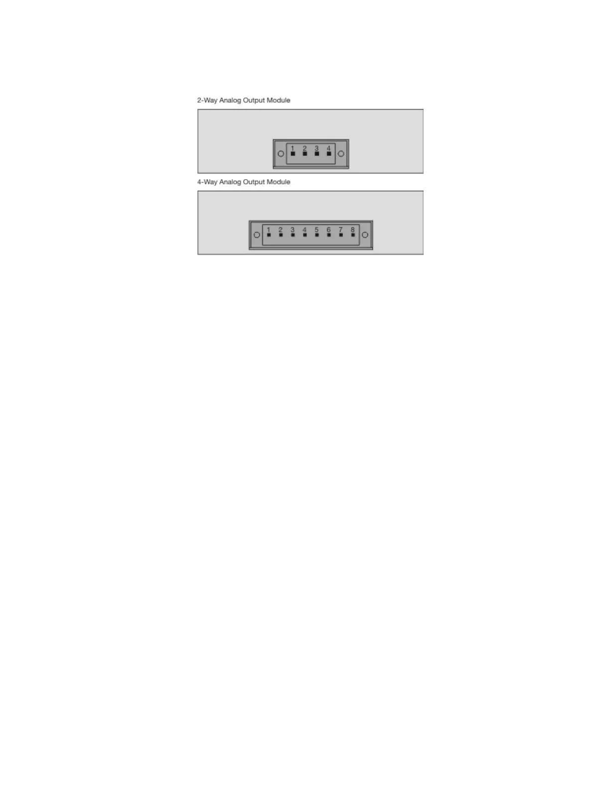
Analog output module: Electrical connections
Pin Signal
1 AO1+
2 AO1–
3 AO2+
4 AO2–
5 AO3+
6 AO3–
7 AO4+
8 AO4–
Analog outputs AO1 to AO4
0/4 to 20 mA (pre-set ex works to 4 to 20 mA), common negative pole, elec-
trically isolated to ground, can be connected to ground as required, in this
regard, max. gain compared to local protective ground potential 50 V, work-
ing resistance max. 750 Ω. Resolution 16 bit. The output signal may not be
less than 0 mA.
Design
4-pole or 8-pole plug-in terminal strip. Please refer to the information about
the requisite material (see page 116)!
Terminal layout
An analog output is allocated in the sequence of the sample components for
each sample component. The sequence of the sample components is docu-
mented in the analyzer data sheet (see page 75) and on the identification
plate (see page 74).
 Loading...


