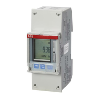
1. Select a value
Select a value when
the digit blinks.
2. Cancel a value
3. Change Value
Enter the value when
the digit blinks.
Example:
Set CT Ratio 100/5
Example:
Set 10 to 20
(Default Menu)
(Default Menu)
(CT Ratios)
(Wires)
(Choose from list)
(No Neutral)(With Neutral)
1.2 Connection -B24
1.3 Connection -B23
1.4 Connection -B21
2 Explanations
3 Basic settings
Table 3 Technical data
B21 B23 B24
Nominal voltage 230 V AC 3x230/400 V AC
Voltage range 220-240 VAC
(-20% to +15%)
3x220-240 V AC
(-20% to +15%)
Base current Ib 5 A -
Rated current In - 1 A
Reference current Iref 5 A -
Maximum current
Imax
65 A 6 A
Terminal wire area 1.5 - 25 mm² 0.5 - 10 mm²
Frequency 50 or 60 Hz ± 5%
Accuracy Class B (Cl. 1) and
Reactive Cl. 2
B (Cl. 1) and
Reactive Cl. 2
B (Cl. 1) or C
(Cl. 0,5 S) and
Reactive Cl. 2
Active energy 1% 0.5%, 1%
Environmental
Operating
temperature
-40 to +70°C
Storage temperature -40°C to +85°C
Humidity 75% yearly average, 95% on 30 days/year
Resistance to water
and dust
IP20 on terminal block without protective
enclosure and IP51 in protective enclosure,
according to IEC 60529.
Mechanical
environment
Class M2 in accordance with the Measuring
Instrument Directive (MID). (2004/22/EC).
Electromagnetic
environment
Class E2 in accordance with the Measuring
Instrument Directive (MID), (2004/22/EC).
Outputs
Current 2 - 100 mA
Voltage 5 - 240 V AC/DC.
5 - 40 V DC. For meters with only 1 output.
Pulse output
frequency
Programmable: 1 - 999999 imp/kWh
Pulse length Programmable: 10 - 990 ms
Terminal wire area 0.5 - 1 mm²
Inputs
Voltage 0 - 240 V AC/DC
OFF 0 - 12 V AC/DC
ON 57 - 240 V AC/24 - 240 V DC
Min. pulse length 30 ms
Terminal wire area 0.5 - 1 mm²
Standards IEC 62052-11, IEC 62053-21 class 1 & 2,
IEC 62053-22 class 0,5 S, IEC 62053-23
class 2, IEC 62054-21, GB/T 17215.211-
2006, GB/T 17215.312-2008 class 1 & 2,
GB/T 17215.322-2008 class 0,5 S, GB
4208-2008, EN 50470-1, EN 50470-3
category A, B & C
Material Polycarbonate in transparent front glass.
Glass reinforced polycarbonate in bottom
case and upper case. Polycarbonate in
terminal cover.
B21/B23 B24
B24B23/B24
Pulse output
Pulse 1
Quantity : Active Energy Import
Frequency: 100 Imp/kWh
Length: 100 ms
Output: 1
Pulse 2
Quantity : Active Energy Export
Frequency: 100 Imp/kWh
Length: 100 ms
Output: 2
Wires
Wires: 4 Wires
(3 Phases & Neutral)
Pulse output
Pulse 1
Quantity : Active Energy Import
Frequency: 10 Imp/kWh
Length: 100 ms
Output: 1
Pulse 2
Quantity : Active Energy Export
Frequency: 10 Imp/kWh
Length: 100 ms
Output: 2
CT Ratios
CT Ratios: 5/5
S1 S2
S1 S2
S1 S2
693
4
L1
L2
L3
L1
L2
L3
P1 P2
11 1 2 5 7 8
N
N
3 x ≤ 10 A
P1 P2
P1 P2
(1,2 Nm)
S1 S2
S1 S2
9
L1
L2
L3
L1
L2
L3
P1 P2
1 2 5 7 8
3 x ≤ 10 A
P1 P2
3
(1,2 Nm)
L1
L2
693
471
L1
L2
L3
3 x ≤ 65 A
(2,0 Nm)
L
N
1
3
5
L
N
1 x ≤ 65 A
(2,0 Nm)
1 2 3 !
T1
0.00
kVV h
1 2 3 !
T1
LENGTh
1 2 3 !
T1
100
1 2 3 !
T1
100
1 2 3 !
T1
100
1 2 3 !
T1
OUTPUT
1 2 3 !
T1
1 OUT
1 2 3 !
T1
1 OUT
1 2 3 !
T1
1 OUT
1 2 3
PULSE
1 2 3
QUANT
1 2 3 !
T1
ACt 1
kVV h
1 2 3 !
T1
ACt 1
kVV h
1 2 3 !
T1
ACt 1
kVV h
1 2 3 !
T1
frequen
1 2 3 !
T1
10
kVV
1 2 3 !
T1
000010
kVV
1 2 3 !
T1
10
kVV
OK
OK
OK
OK
OK
OK
OK
OK
OK
OK
OK
OK
OK
OK
OK
OK
OK
OK
SET
SET
SET
SET
SET
SET
SET
SET
SET
SET
SET
SET
SET
SET
SET
SET
SET
SET
2x
7x
2x
1
2
3
4
5
6
7
8
9
10
11
12
13
14
15
16
17
18
B21/B23/B24
INSTALLATION MANUAL
2CMC485019M0201 May 2016 Rev B
Contact us
ABB AB
P.O Box 1005
SE-611 29 NYKÖPING, Sweden
+46(0)21-32 50 00
www.abb.com /low-voltage
© Copyright 2016 ABB AB. All rights reserved.
Specication subject to change without notice.
Avertissement! Installation uniquement par des personnes
qualiées en électrotechnique.
Advertencia! La instalación deberá ser realizada
únicamente por electricistas especializados.
Warning! Installation by person with electrotechnical
expertise only.
Warnung! Installation nur durch elektrotechnishe Fachkraft.
Avvertenzal! Fare installare solo da un elettricista qualicato.
3.2
3.4 B24 - CT Ratios
3.3 B23/B24 - Wires
3.5 Change / Select values
3.2 B21/B23/B24 - Pulse output
3.1 Default settings
PZ2
5.5 mm

 Loading...