Planning the electrical installation
41
3ADW000462R0301 DCS880 Hardware Manual e c
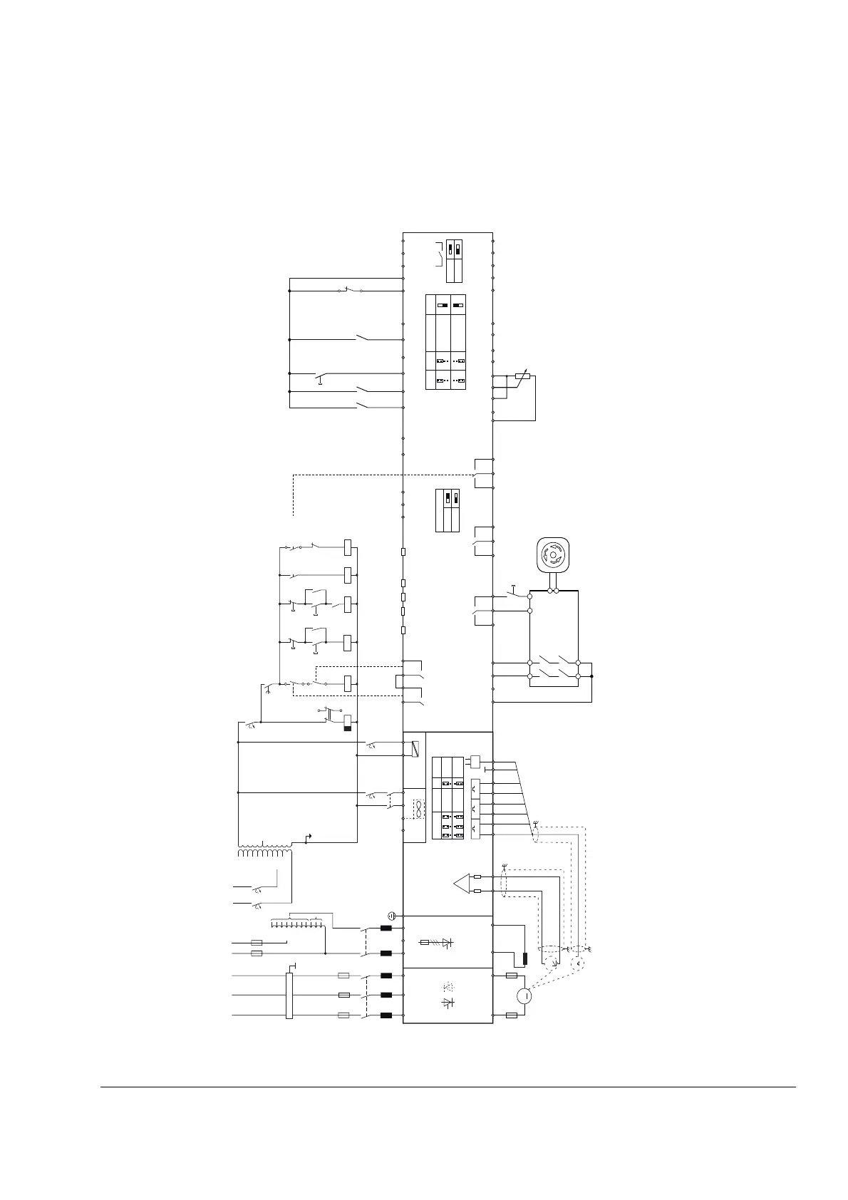
Converters size H6 configuration using a FEX-425-Int field exciter
Wiring the drive according to this diagram offers the highest degree of monitoring functions done by
the drive. Field converters FEX-425-Int are equipped with their own synchronization and must be
supplied from independent mains supply voltage max. 500 V (single-phase or 3-phase).
PE
K1 Klixon
K21K20K1
T2
690 V
660 V
600 V
575 V
525 V
500 V
450 V
415 V
400 V
380 V
115 V
230 V
K16
K16 K8
XSMC:1
XSMC:2
XSMC:3
XSMC:4
XRO3 = Fan on
K21
32
33
K20
F7
F2
1
2
Stop
Start
SDCS-CON-H01
J6
AI1 - J1 AI2 - J2 AO1 - J5
SF_880_020_DCS_anschluss_d.ai
D2D - J3
current 20 mA
voltage 10 V
default
default
default
default
open
terminated
open
closed
default
Slot3
Slot2
Slot1
Control panel
DCSLink
Mains
contactor
Latching on
Latching run
On
Run
Reset
Off2 (current off)
OUT1
SGND
IN1
IN2
NC
COM
NO
NC
COM
NO
NC
COM
NO
COM
NO
COM
NO
B
A
BGND
DI1
DI2
DIO1
DIO2
DI3
DI4
DI5
DI6
+10V
-10V
AGND
AI1-
AI2+
AI2-
AI1+
DICOM
+24VD
DIOGND
+24VD
DIL
AO2
AGND
AGND
AO1
AI3-
AI3+
1 2 3 4
XRO1
XSMC
1211 2221 2313
3421
XRO2
X13 X200
3231 33
XRO3
XSTO
XDIO
1
XD2D
132
XAI
12
345 67
XDI
12 34 562
XAO
1234
IACT
5
XD24
12345
89
OnBoard
tacho feedback
OnBoard Encoder
Feedback
U1 V1
W1
D1C1
1 2
XAUX (X99)
3
4
K1
L1
L1 L2 L3
F1
15
26
M
Power
supply
F5
1
2
1
max.
±270 V
7
EGND
24 V 5 V
8
J4D
1 2 3 4 5 6
2
T
+
_
E
XENC
+ A - + B - + Z -
1
2
OFF2
OFF2
1
2K21K20
K8
On
Off
E1
EMV-Filter
Aux supplyMains
F2
L1 L2
3
4
1
2
e For proper feedback set 10.24 R01
source = 31.91.b7 or 31.98.b11
e
field exciter
F+ F-
500 V
460 V
415 V
400 V
365 V
350 V
265 V
250 V
90 V
60 V
30 V
L1N
3
4
K3
L3
F3.2
1
2
T3
FEX-425-Int
UW
F3.1
(F301 ...
F303)
V
K3
XRO2
Field exciter on
Fans on
Fan acknowledge
X2
SDCS-POW-H01
1 3 4
PE
1
2
K8
F8
1
2
1
2
J4
A B C
J4
D
Encoder
supply
10 k 24 V
5 V
120
pull up
differential
14 7
36 9
10
12
Reset
Safety
Relais
Sample circuit E-STOP Cat 0 with DCS880 STO
S1
A4
+ -
 Loading...