Technical specifications 3 – 18 Advant Controller AC 31 / Issued: 01.99
3
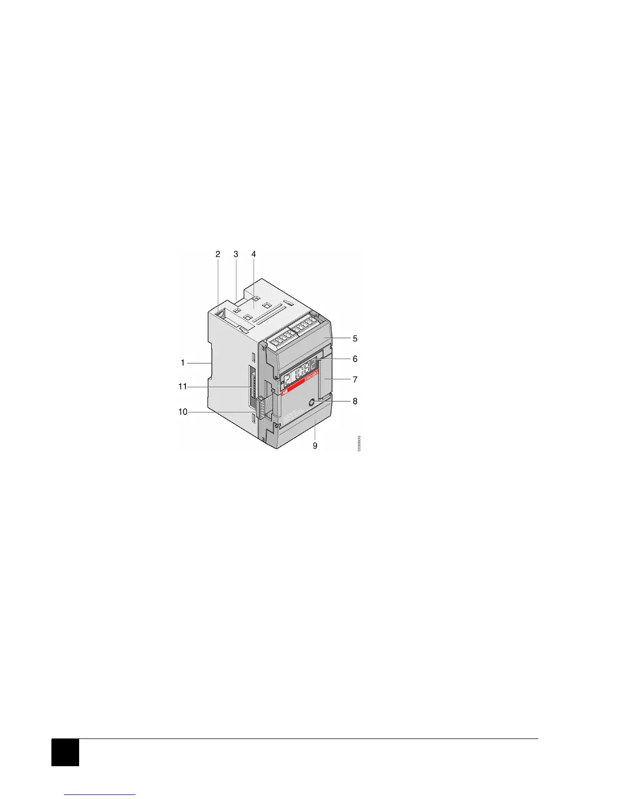
3.6 Analog central extension
3.6.1 View (see Figure 8)
1 – Location for the DIN rail
2 – Plate fixture with unit earthing, alternative to 1
3 – Release lever for DIN rail mounting
4 – Location for external dual connector
5 – Input cabling connectors under the cover flap, plug-in type
6 – Display of channel number and the associated analog value
7 – Connector for the supplementary central additional input/output extensions
8 – Push-button used to select the channel displayed, and for the configuration
9 – Connectors for the output cabling under the cover flap, plug-in type
10 – Connector for connection to the basic unit/remote unit or to the last input/output
extension connected to the basic unit/remote unit
11 – DIP switches for configuring the channels as current, voltage or Pt 100/Pt 1000
Figure 8: Front view of the central analog extension XM 06 B5
 Loading...