The analog channels have fixed connections towards the different function blocks
inside the protection relay’s configuration. Exceptions from this rule are the seven
analog channels available for the disturbance recorder function. These channels are
freely selectable and a part of the disturbance recorder’s parameter settings.
The analog channels are assigned to different functions. The common signal marked
with 3I represents the three phase currents. The signal marked with Io represents the
measured residual current via a core balance current transformer.
3.5.3.1 Functional diagrams for protection
The functional diagrams describe the protection functionality of the protection relay
in detail and picture the factory default connections.
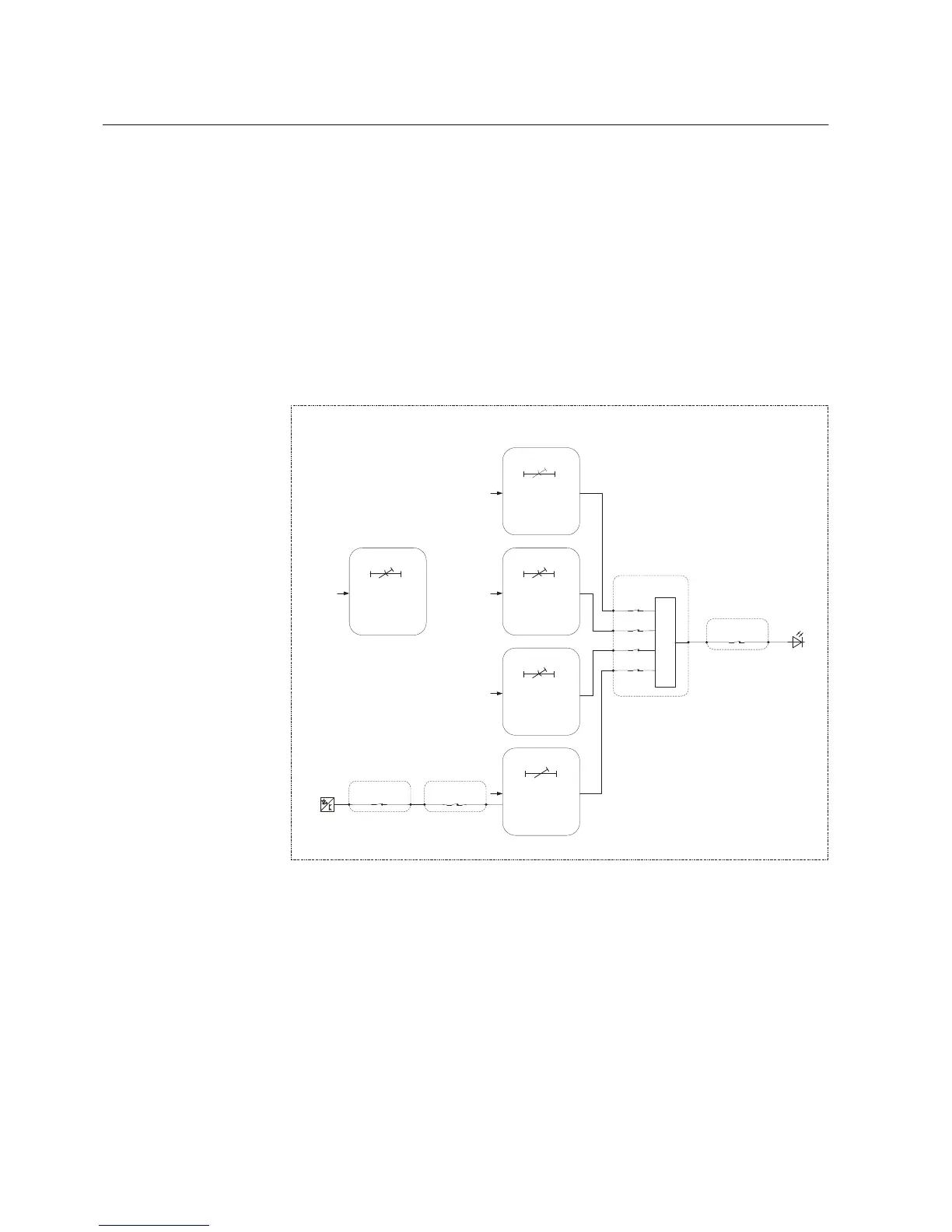
GUID-DEF278A2-D120-437C-BC9A-180BD34C6962 V3 EN
Figure 62: Overcurrent protection
Four overcurrent stages are offered for overcurrent and short-circuit protection. The
instantaneous stage PHIPTOC1 can be blocked by energizing the binary input
(X120:1-2). The inrush detection block’s INRPHAR1 output BLK2H enables either
blocking the function or multiplying the active settings for any of the described
protection function blocks.
All operate signals are connected to the Master Trip and to the alarm LED 1.
Section 3 1MRS757456 D
REF611 standardized configurations
84 REF611
Application Manual
 Loading...


