2105551MNAD | RMC-100 | 13
Before connecting to these pins, ensure that the external device is compatible with the input
voltage at the CHARGER/EXT PWR port. Connecting an incompatible device may result in damage
to the device.
1. Use a slotted screwdriver to pry the terminal connector off the electronic board.
2. Trim the wire covering back ¼ inch on each wire.
3. Loosen the terminal connector screws for the correct pin according to the I/O tables. See sections
4.4.1, 4.4.2, 4.4.3 and 4.4.4
in this guide.
4. Insert the wires in the required pins. If powering the device from the AI or the AO:
a. Use pin 1 (PWR) and pin 3 (GND) for devices attached to the AI.
b. Use pin 1 (PWR) and pin 4 (GND) for devices attached to the AO.
5. Tighten the terminal connector screws.
– Equipment damage. Do not overtighten the terminal connector screws as this
.
6. Insert the terminal connector back on the I/O port if it was removed.
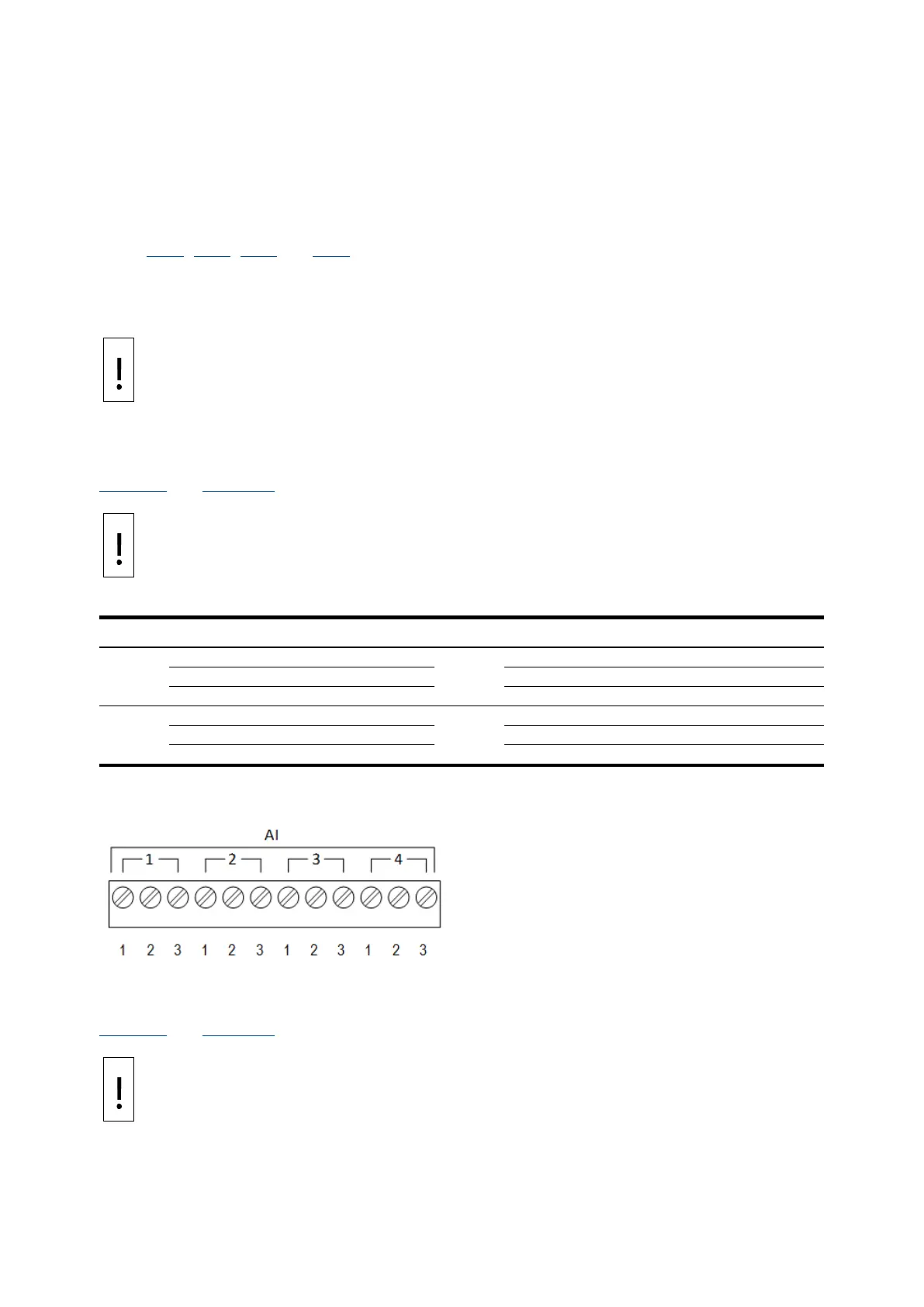
4.4.1 Analog input pinouts
Table 4-3 and Figure 4-3 identify the AI pinouts.
– Equipment damage. Before connecting to pin 1 (PWR), ensure that the external
device is compatible with the input voltage at the CHARGER/EXT PWR port. Connecting an
incompatible device may result in damage to the device.
Table 4-3: Analog input pinouts
1
3
2
4
Figure 4-3: Analog input pinouts
4.4.2 Analog output pinouts
Table 4-4 and Figure 4-4 identify the AO pinouts.
– Equipment damage. Before connecting to pin 1 (PWR), make sure that the
external device is compatible with the input voltage at the CHARGER/EXT PWR port.
Connecting an incompatible device may result in damage to the device.
 Loading...


