9
Power supply
and output relay
module
To be able to operate the relay needs a secured
auxiliary voltage supply. The power supply
module forms the voltages required by the pro-
tection relay module and the auxiliary relays.
The withdrawable power supply and output
relay module is located behind the system front
panel, which is fixed by means of four cross-
slotted screws. The power supply and output
relay module contains the power supply unit, all
output relays, the control circuits of the output
relays and the electronic circuitry of the external
control inputs.
The power supply and output relay module can
be withdrawn after removing the system front
panel. The primary side of the power supply
module is protected with a fuse, F1, located on
the PCB of the module. The fuse size is 1 A
(slow).
The power supply unit is a pulse-width modu-
lated (PWM) dc/dc converter with galvanically
isolated primary and secondary sides. It forms
the dc secondary voltages required by the pro-
tection relay module; that is +24 V, ±12 V and
+8 V. The output voltages ±12 V and +24 V are
stabilized in the power supply module, while the
+5 V logic voltage required by the protection
relay module is stabilized in the protection relay
module.
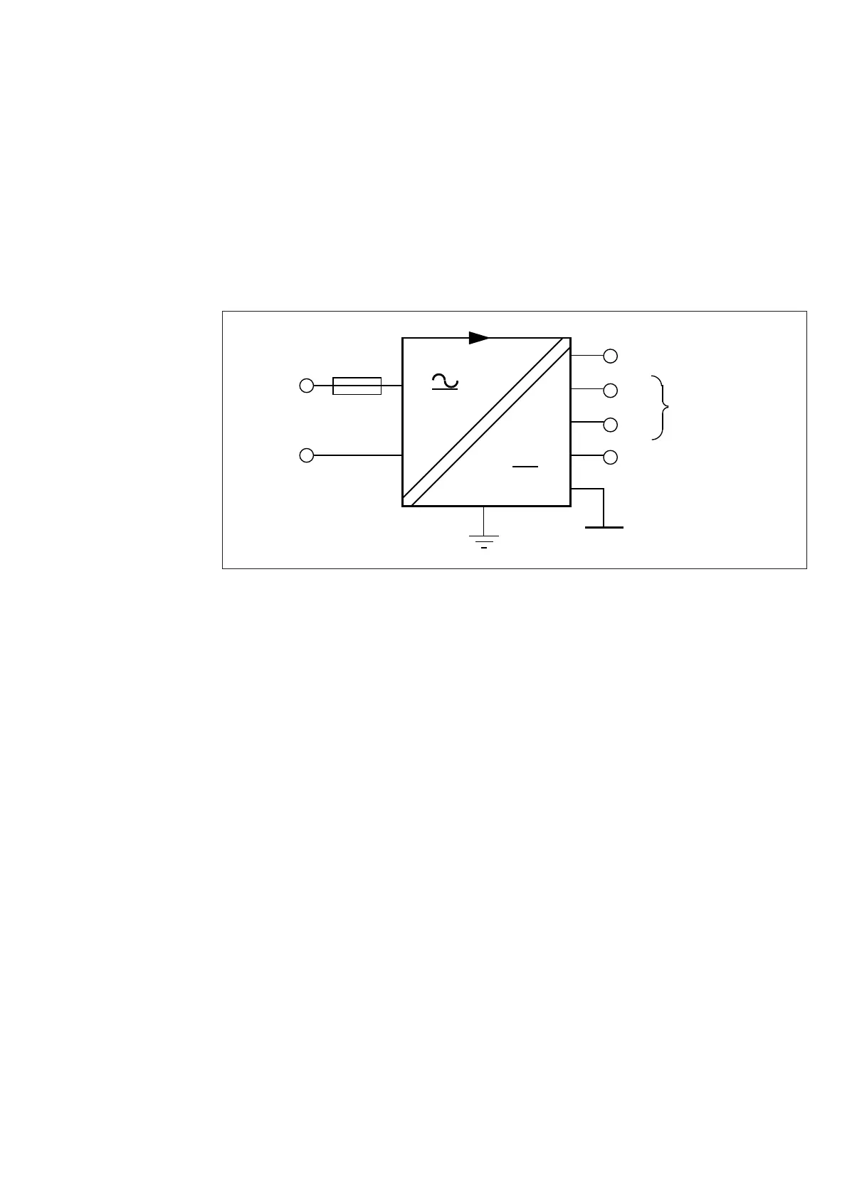
1 A slow
+8V
+12V
-12V
+24V
Uaux
80...265 V ac & dc
18...80 V dc
Unstabilized logics
voltage
Operation amplifier
voltage
Output relay coil
voltage
Fig. 5.Voltage levels of the power supply unit
A green LED indicator U
aux
on the system front
panel is lit when the power supply module is in
operation. The supervision of the voltages sup-
plying the electronics is located in the protec-
tion relay module. If a secondary voltage differs
too much from its rated value, a self-supervision
alarm will be generated. An alarm is also issued
when the power supply module is withdrawn
from the relay case, or on loss of auxiliary supply.
There are two versions of power supply and
output relay modules available. For both types,
the secondary sides and the relay configurations
are identical, but the input voltage ranges differ.
Insulation test voltage between the primary and
secondary side and the protective earth
2 kV, 50 Hz, 1 min
Rated power P
n
5 W
Voltage ranges of the power supply modules:
- SPTU 240 R1 U
aux
= 80...265 V dc/ac
- SPTU 48 R1 U
aux
= 18...80 V dc
The SPTU 240 R1 module can be fed from
either an ac source or a dc source. SPTU 48 R1
is designed for dc supply only. The permitted
auxiliary voltage range of the relay is marked on
the relay system front panel.
 Loading...