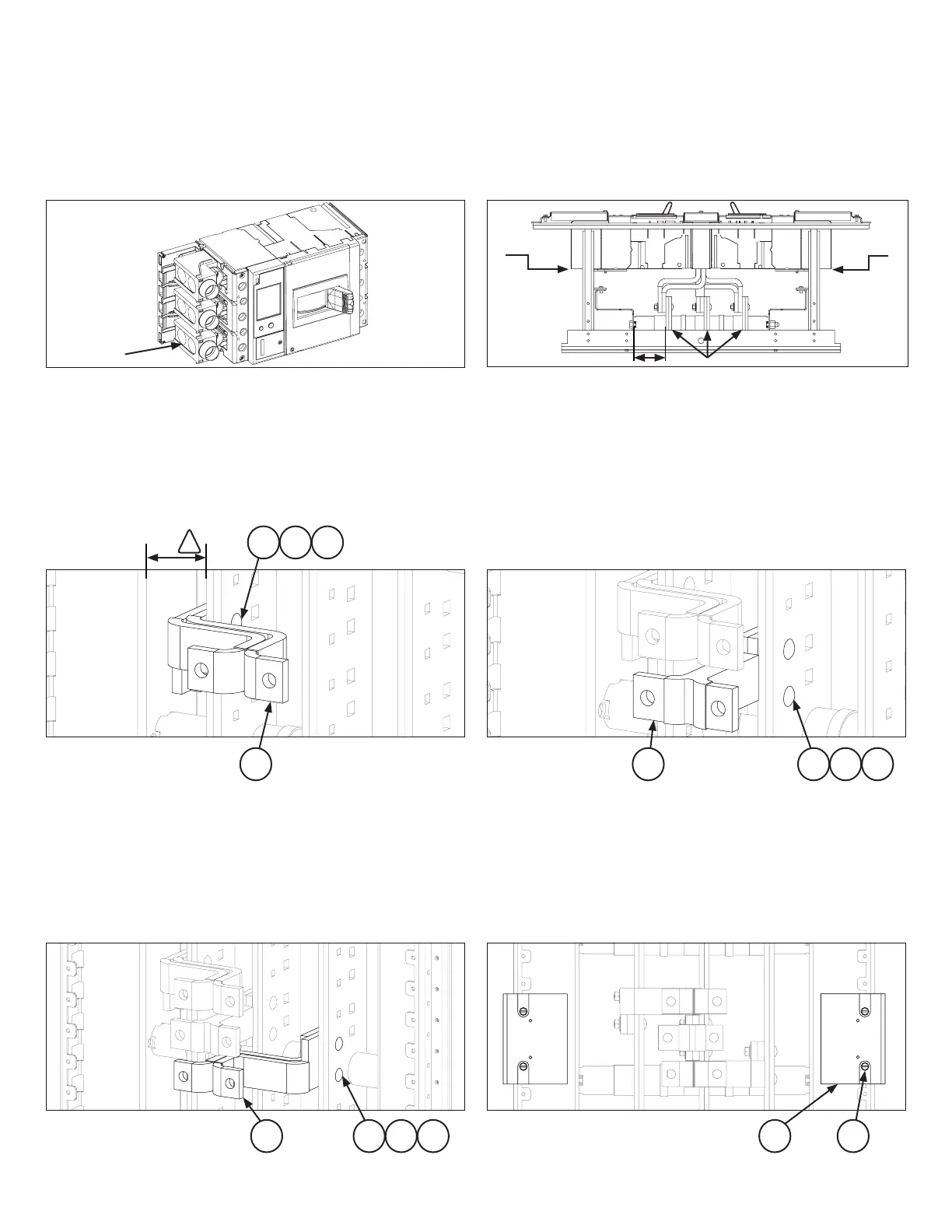
STEP 2
Find the side of the panel interior at which the dimension from the
face of nearest vertical bus to the inner face of the bus support rail
Main Bus
Lugs installed
on load side
LOAD LOAD
LINE LINE
—
—
Figure 3. Installation of right link assembly
—
Figure 4. Installation of middle link assembly
—
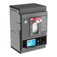
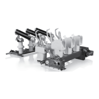
Figure 1. Breaker preparation
Right side
cable entry
Left side
cable entry
REF
STEP 6
Install the breaker mounting bracket [4] on the bus support rail
Refer figure 6.
—
Figure 5. Installation of left link assembly
—
Figure 6. Installation of breaker mounting bracket
!
2
STEP 1
more information. Install the appropriate lugs as in load side as
shown in figure 1.
Step 3
Install the link assembly - Right link assembly [12] to adjacent pole
from 2.75 inches ref. as shown in figure 3. Fasten the complete link
washer [2] and nut [3]. Refer figure 3.
Step 4
Install the link assembly - Middle link assembly [11] to middle pole
as shown in figure 4. Fasten the complete link assembly loosely to
[3]. Refer figure 4.
Step 5
Install the link assembly - Left link assembly [10] to outermost pole
as shown in figure 5. Fasten the complete link assembly loosely to
[3]. Refer figure 5.
 Loading...