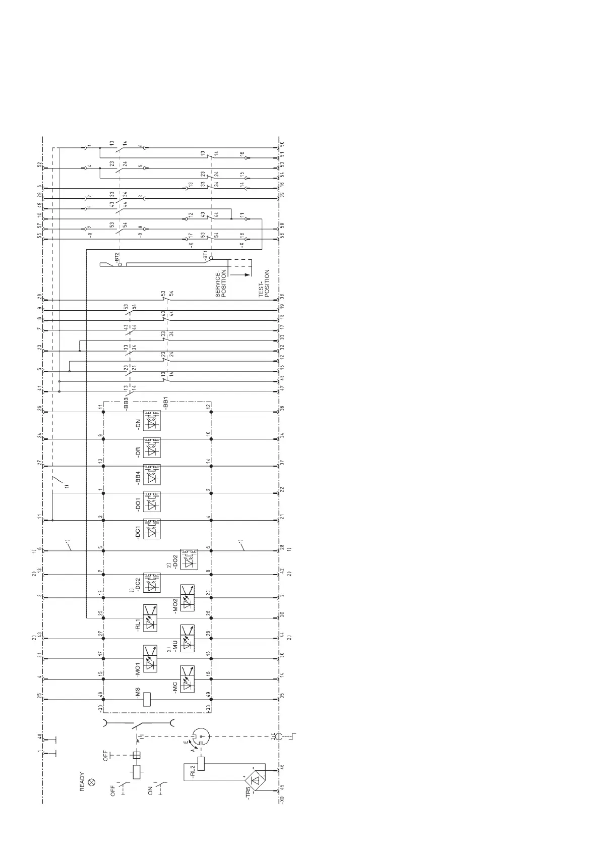
48 VM1 Vacuum circuit-breaker | Instruction manual 504/05
-MS Supply voltage
-RL2 Blocking magnet for withdrawable part with rectifier –TR5
-RL1 Closing lock-out (closed circuit)
-MO1 Switching command OFF 1 (open circuit)
-MC Switching command ON (open circuit)
-MU Undervoltage release (closed circuit)
-MO2 Switching command OFF 2 (open circuit)
-BB1 Auxiliary switch on the actuating shaft
-BB3 Auxiliary switch on the actuating shaft
-BB4 Fleeting contact (100 ms)
-BT2 Limit switch for withdrawable part in test position
-BT1 Limit switch for withdrawable part in service position
-DR READY for operation (NOC)
-DN NOT READY for operation (NCC)
-DO1 OFF signal (NOC)
-DC1 ON signal (NOC)
-DO2 OFF-Signal (NOC) (Full version)
-DC2 ON-Signal (NOC) (Full version)
See page 52 for comparison of IEC/VDE designations.
Mode of presentation:
1)
Connection exists when auxiliary switches -BB1 and -BB3 are not used
2)
Full version
Note:
If the READY contact -DR is to be polled, the wiring dia-
gram of the panel should include the information that this
contact is already connected to blocking magnet -RL2 and
is therefore not isolated.
Note:
The wiring diagrams comprise the basic com ponents and all fur-
ther equipment options for the various VM1 types. The scope of
10.3.3 Wiring diagrams for C.B. on withdrawable part
equipment possible within an individual type series is listed in the
relevant switchgear list, and the euquipment fitted in each individ-
ual case can be found in the order documentation.
Figure 10/10: Wiring diagramm for VM1 vacuum circuit-breaker on
manually movable withdrawable assembly.
- Maximum of equipment
- Control wiring plug 58-pole
- Use in panel system ZS1, UniGear-Type ZS1, UniSafe,
Power-bloc and Mounting frame
BA 504-05 GB_29102012.indd 48 30.10.12 13:45
 Loading...