3-22 Machine Maintenance Procedures
Upper Cover Removal 0
Prerequisite:
HDD Module Removal
Keyboard Removal
DIMM Module Removal
WLAN Module Removal
Optical Disk Drive (ODD) Module Removal
WLAN cables shown in the following images may not reflect the final product.
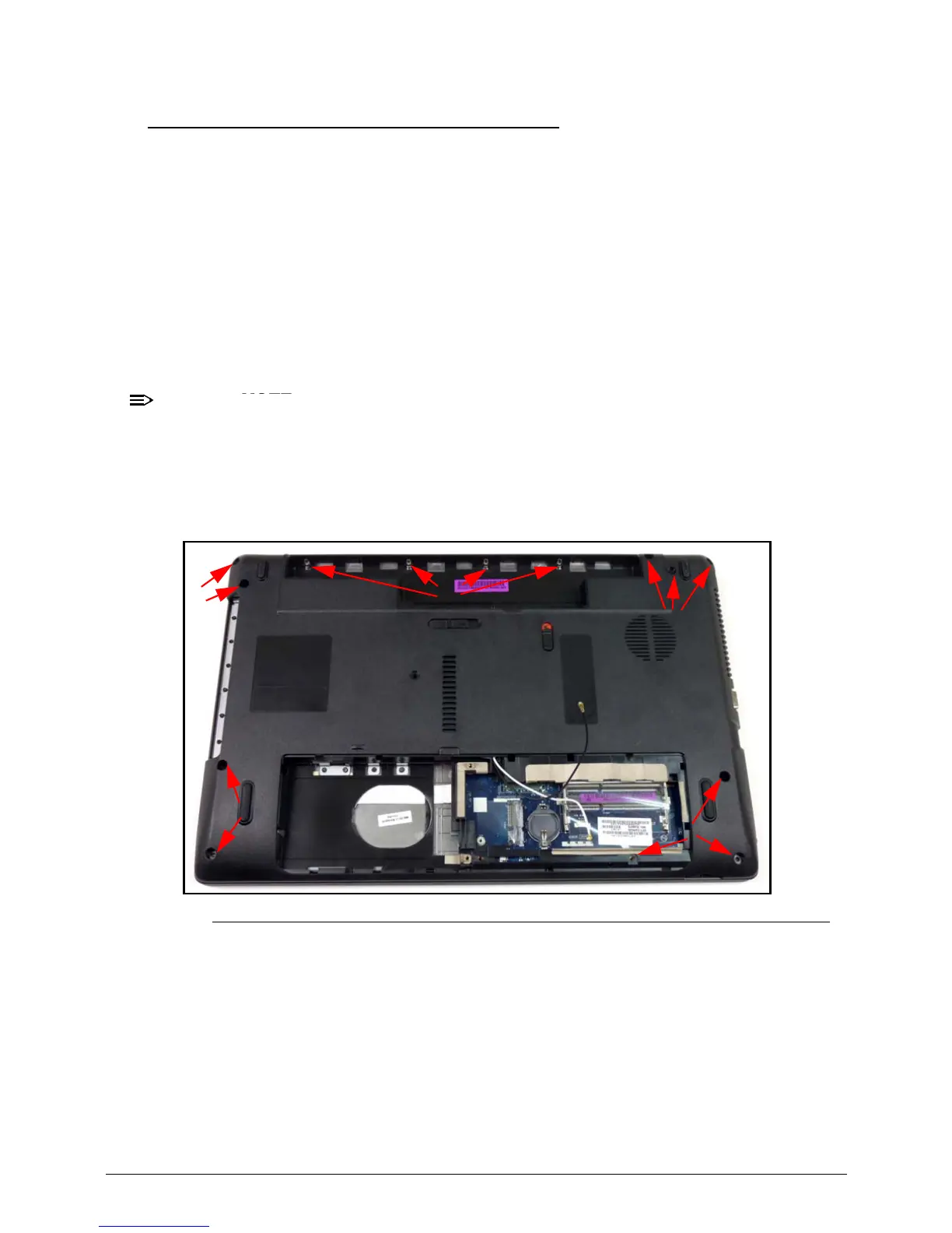
1. Remove the following screws:
ten (10) screws (A) from lower cover
four (4) screws (B) from battery bay.
Figure 3-22. Lower Cover
2. Place computer on surface, face up.
3. Disconnect the following cables:
power board FFC cable (C) from mainboard connector (D)
touchpad FFC cable (E) from mainboard connector (F)
speaker cable (G) from mainboard connector (H).