4 User’s Guide
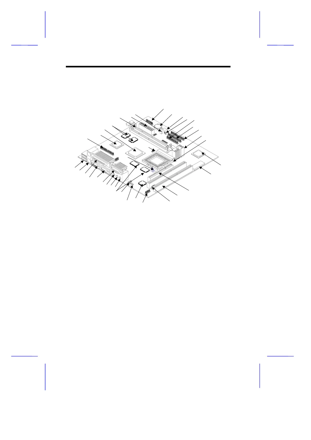
2 System Board Layout
Figure 1 shows the locations of the major components on the system
board.
1 USB ports
2 PS/2 mouse/keyboard port
3 Parallel port
4 VGA port
5 COM2 port
6 Game/MIDI port
7 Line-out port
8 Line-in port
9 Microphone-in port
10 Second-level cache (pipeline-burst)
11 Fax/voice connector
12 CD-in connector
13 3-D audio controller
14 External CS4610 connector
15 Volume control connector
16 ISA slots
17 PCI slot
18 System BIOS chip
19 PCI-to-ISA bridge controller
20 CPU socket
21 Voltage controller with heatsink
22 IDE 1 connector
23 IDE 2 connector
24 FDD connector
25 Modem ring-in connector
26 Buzzer
27 Battery
28 Power button/ Reset/ Turbo/ HDD/
Power, Suspend LED/IrDA connector
29 Wake-up On LAN connector
30 ATX power connector
31 DIMM sockets
32 Video memory
33 PCI, AGP, memory controller
34 3-D AGP video controller
35 ATI AMC feature connector
36 Tag RAM
37 CPU fan connector
Figure 1 System Board Layout
1
2
3
4 5
6
7 8 9
10 11
12 13
14
16
1
18
19
20
35
3
3
32
31
30
2
28
2
26
25 2
23 22
21
1
36
37
 Loading...