EasyManua.ls Logo

Acer XB270HU User Manual

Acer XB270HU
63 pages
To Next Page IconTo Next Page
To Previous Page IconTo Previous Page
Page #31 background imageLoading...
Page #31 background image
29
3.1.2 TI micro-controllers FW update
This chapter describes how to flash new code into the two TI-MSP430 micro-controllers on the NVIDIA G-SYNC
module and base board. These two micro-controllers take care of handling the button presses and the LED control
of the monitor. One of the two micro-controllers is located on the G-sync module, and the second micro-controllers
is located on the base board.
3.1.3 Required Hardware
The hardware required to update the code on the two micro-controllers is a TI-MSP430 USB debug interface.
This device can be ordered from TI at http://www.ti.com/tool/msp-fet430uif
.
Figure: MSP-FET430UIF with Cables
In order to connect the base board micro-controllers, the standard ribbon cable that comes with MSP-FET430UIF
can be used. In order to connect the MSP-FET430UIF to the P2324 G-SYNC module, a special connection cable
muse be used. This connection cable is provided by NVIDIA and should have come with your G-SYNC module.
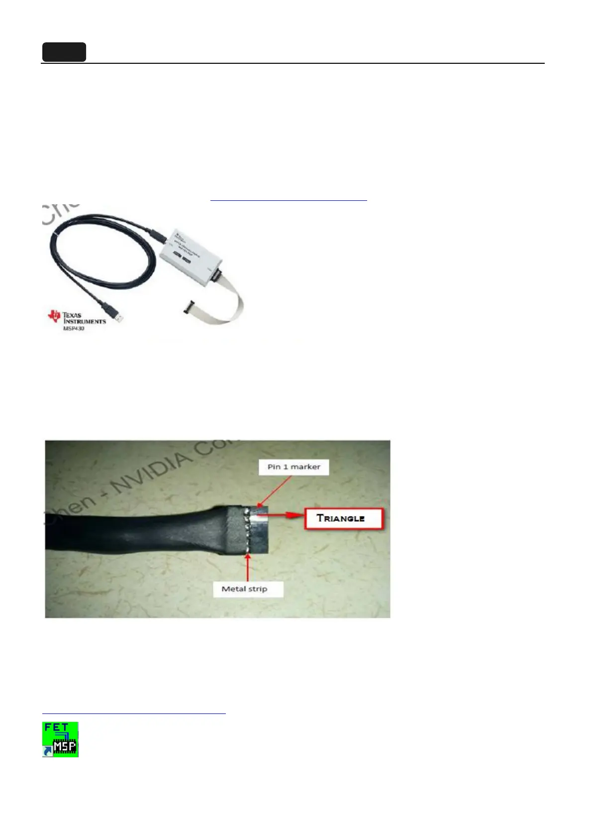
One end of that cable will connect to the MSP-FET430UIF programmer, and the other end connects to the
G-SYNC module and looks like this:
The header contains a marker to indicate pin1: an arrow/triangle in the black plastic header in the location of pin1.
3.1.4 Required Software
In order to load the binary code into the flash memories for the micro-controllers, we use the Elpotronic
FET-Pro430 Lite software. This software is free to use and can be downloaded from
http://www.elprotronic.com/download.html
.

Questions and Answers:

Acer XB270HU Specifications

General IconGeneral
Screen Size27 inches
Resolution2560 x 1440
Panel TypeIPS
Refresh Rate144 Hz
Response Time4 ms
Aspect Ratio16:9
Brightness350 cd/m²
Contrast Ratio1000:1
G-SyncYes
Viewing Angle178° (H) / 178° (V)
Color Support16.7 million
VESA Mount100 x 100 mm
PortsDisplayPort, HDMI, USB 3.0

Summary

Important Safety Notice

Product Announcement and Reparability

Product certification, approved components, vendor liability, and service qualifications.

Safety Precautions

Key safety warnings for electrical connections and handling.

Product Specification

Monitor Overview and Specifications

General overview and detailed technical specifications for the monitor.

Electrical Diagram and Test Conditions

Block diagram of electrical components and standard product testing conditions.

Interface Connectors: DP

Detailed pinout and description for the DisplayPort interface connector.

Input Signals and Amplitudes

Defines video input signal ranges, amplitudes, termination, and sync signals.

Monitor Modes and Timing Capability

Lists factory-assigned display modes and their resolutions/refresh rates.

Mechanical and Packing Specifications

Provides dimensions and details about the monitor's mechanical specs and packaging.

Panel Specification

Flat Panel Specifications

Detailed specs for the 27-inch QHD TFT-LCD module, including display parameters.

Optical Characteristics and Backlight Requirements

Details on viewing angle, contrast, response time, and backlight requirements.

Defect Terminology and Optical Measurements

Defines display defects and notes on optical measurement methods.

Response Time and Luminance Uniformity

Explains response time measurement and luminance uniformity definition.

Crosstalk and Test Patterns

Defines crosstalk measurement and describes test patterns for flicker.

OSD Menu

Key Definitions for OSD Control

Defines the function of each key on the OSD control interface.

Exploded Diagram

Product Exploded Diagram

Visual representation of the monitor's components in an exploded view.

Item and Part Descriptions

Lists all individual parts with their descriptions, TPV, and Acer part numbers.

Packing Exploded Diagram

Exploded view illustrating the packaging components and their arrangement.

Assembly and Disassembly Procedures

Assembly Procedures

Step-by-step guide for assembling the monitor components.

Disassembly Procedures

Step-by-step guide for disassembling the monitor components.

Troubleshooting

No Power Issues

Troubleshooting guide for issues related to the monitor not turning on.

No Video (Power LED Blue)

Troubleshooting steps for when there is no video output but the power LED is blue.

DIM Display Issues

Troubleshooting guide for dim display issues, image overlap, focus, or flicker.

Color Display Issues

Steps for resolving color display issues like miss color or color shift.

Firmware Upgrade Process

Materials, Driver, and Micro-controller Update

Lists materials, driver installation, and TI micro-controller FW update steps.

Micro-controller FW Update Details

Specifics on updating TI micro-controllers, required hardware, and software.

Base Board and G-SYNC Module Update Steps

Guides for updating base board and G-SYNC module firmware, including cable connections.

Micro-controller Selection and Protocol Setup

Instructions for selecting the micro-controller and setting up the communication protocol.

Selecting the Code File

Guide on opening and selecting the correct firmware code file.

Flashing Code and G-SYNC Update

Instructions to flash code and update the G-SYNC module, including cable connections.

G-SYNC Module FW Update Overview and Requirements

Overview of G-SYNC module FW update, required hardware, and process.

USB Blaster Driver and Software Setup

Guides for installing USB Blaster driver and setting up Nios II software.

Project Import and Command Shell Setup

Instructions for importing projects and opening the Nios II command shell.

Command Line Operations for Firmware

Shows command line output and steps for flashing bitstream and AC power cycle.

Flashing .bin/.elf/Panel Profiles

Steps to flash .bin/.elf files and panel profiles using scripts.

Q&A

Firmware Update Conditions and Sequence

Discusses conditions requiring FW updates and their sequence.

OSD SN and G-SYNC/ULMB Function Check

Explains OSD SN absence and how to check G-SYNC/ULMB functionality.

Writing EDID Process

EDID Process Status

States that the EDID process is not required.

FRU (Field Replaceable Unit) List

FRU Part List and Ordering Information

Lists Field Replaceable Units with TPV and Acer part numbers, and notes on ordering.

Schematics and Layouts

Schematics and Layouts Overview

Introduces detailed schematics and component layouts for monitor PCBs.

Main Board Schematics: System Power

Detailed schematics of the Main Board and its System Power circuitry.

Panel Power and Input_DP Schematics

Schematics for the panel power supply circuits and DisplayPort input.

SODIMM - 204PIN Interface

Pin definition and interface details for the SODIMM connector.

MISC Schematics

Schematics for miscellaneous components like monitor LEDs and buttons.

Panel Interface: LVDS - 8X OUTPUT

Details the LVDS interface for panel communication.

CONVERT Schematics

Schematics for the converter circuits, likely for backlight or power.

Power Board: AC Input and PFC

Schematics for the power board's AC input and Power Factor Correction (PFC) stages.

Main Power and Converter Schematics

Schematics for the main power supply and converter sections.

Key Board and USB Board Schematics

Schematics for the Key Board and USB Board components.

Main Board Layout

Component layout diagram for the Main Board.

Related product manuals