3
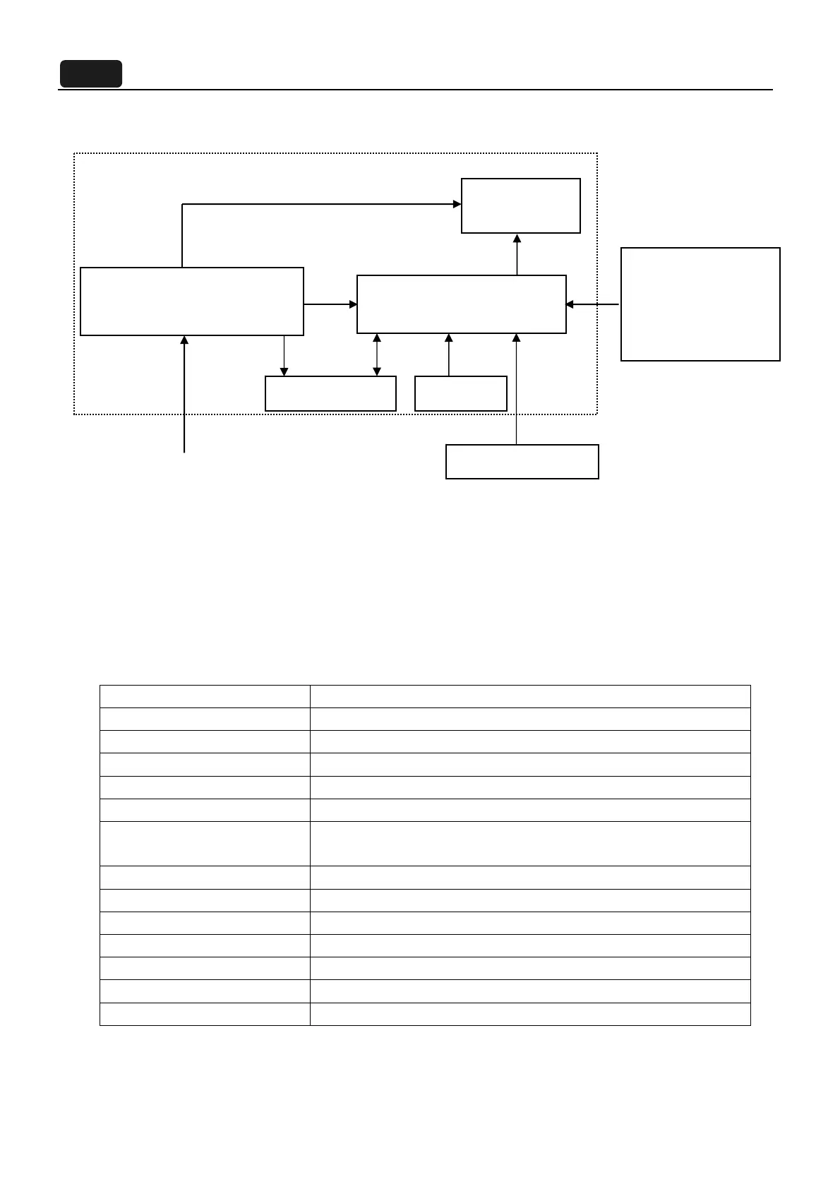
1.1.2 Electrical block diagram:
This section describes the electrical requirement of the monitor. Below is the block diagram.
The LCD monitor will contain a main board, a power board, an USB board and a key board which house
the flat panel control logic, brightness control logic and DDC. The power board will provide DC to DC
Inverter voltage to drive the backlight of panel. The function key board is used for OSD control, monitor
power ON/OFF and the LED indicator for power status.
1.1.3 Test Condition:
All tests must be performed under “standard testing conditions” unless otherwise specified.
Test Equipment: CHROMA 6630.
Warm up time > 30 min.
AC supply voltage 220V± 5%, 50± 3 Hz
Ambient temperature
20C 5C
Humidity
50% 10%
Display mode 2560 x 1440, 60 Hz, Pixel Clock: 538MHZ,all white
e-color mode Set to “User” mode
Contrast control Set to factory preset value, which allows that the brightest two of 32
linear distributed gray-scales (0~700mv) can be distinguished.
Color temperature 6500°K
Brightness control The value under user mode
Analog Input signal 700 mVss
Picture position and size Factory preset value
Viewing angle 90 ° H and 50 °V
Viewing distance 40 cm for LCD performance, 20 cm for LCD failures
Ambient illumination Dark room (< 1 cd/m
2
)
AC-IN 100V-240V
Power board
Flat Panel and
LED backlight
Main Board
RS232 Connector
For white balance
adjustment in factory
mode
LED Drive.
Video signal, DDC
HOST Computer
Key Board
USB Board
 Loading...