EasyManuals Logo
Home>Agilent Technologies>Inverter>33120A

Agilent Technologies 33120A Installation Instructions

Agilent Technologies 33120A
6 pages
To Next Page IconTo Next Page
To Previous Page IconTo Previous Page
Page #2 background imageLoading...
Page #2 background image
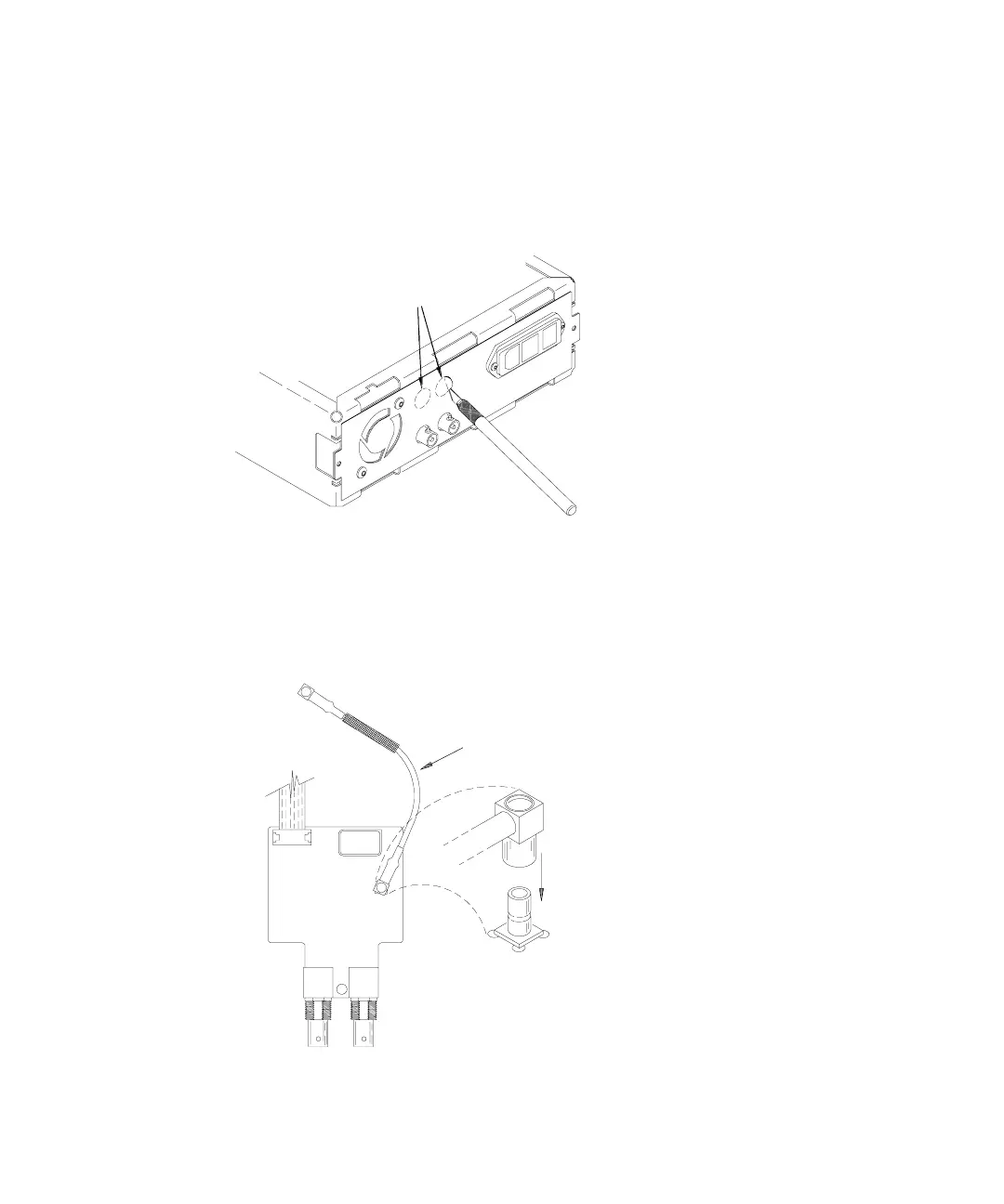
2 Carefully cut two holes in the rear-panel label.
The Ref Out and Ext Ref In terminals on the Phase-Lock assembly will
extend through these holes in the 33120A rear-panel. Pierce the label in
the center of the chassis holes and then cut to the outer edge of the holes.
Then, let the chassis holes guide the knife around the edge of the hole.
3 Connect the coaxial cable to the Phase-Lock circuit board.
Connect one end of the coaxial cable (included with the retrofit kit) to
the connector labeled P2 on the Phase-Lock circuit board. Position the
cable as shown.
2
Cut Out Label
to Chassis Holes
Coaxial Cable (33120-61603)
P2
P2

Other manuals for Agilent Technologies 33120A

Questions and Answers:

Question and Answer IconNeed help?

Do you have a question about the Agilent Technologies 33120A and is the answer not in the manual?

Agilent Technologies 33120A Specifications

General IconGeneral
BrandAgilent Technologies
Model33120A
CategoryInverter
LanguageEnglish

Related product manuals