ON
OFF
ON
OFF
A
E
D
A
C
B
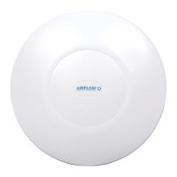
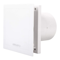
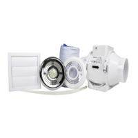
Fan overview
Electrical Installation
Installation Prepare wall or ceiling
Access to the electronics Dip switch functions
Fan Dimensions
The iCONstant range consists of timer and humidity/timer
variants. They are designed for use in any wet room. Trickle
ows rates of 6, 8 or 13 l/s can be activated on installation.
Boost ow rates are selected by pull cord, external switch
or humidity sensor (HT model only). The iCONstant range is
IPX5 rated and suitable for use in Zone 1 of a wet room.
Secure supply wires into the terminal block. L—Live,
N-Neutral and T—switched live (optional). Secure AC mains
cable to main body of fan with cable clamp supplied.
Fit back plate cover.
1. Locate back plate cover on to main body assembly.
2. Twist back plate cover clockwise until locked. (Arrow
should be in the 12 o’clock position).
3. Secure back plate cover with xing screw.
All electrical installation to be carried out by an approved
electrician in accordance with Part “P” U.K. Building
Regulations and to the latest IEEE standards, or the
appropriate regulations in the country of installation.
iCONstant fans require a 90-264V 50/60Hz supply, it is
double insulated so therefore does not require an earth.
Fans installed in Zone 1 or Zone 2 must be at least IPX4
(splash proof) rated. Additionally, fans installed in Zone 1
must be SELV (Safety Extra Low Voltage) or IPX5 (jet proof)
rated. The iCONstant range is IPX5 rated and suitable for
use in Zone 1.
Remove back plate cover.
1. Remove screw at base of back plate cover.
2. Twist back plate cover anticlockwise.
3. Lift away.
Mount fan into the spigot hole ensuring cable is fed through
the cable grommet provided. Position alignment arrow
vertically. Fix to wall or ceiling with the 4 screws provided.
Description of electronic controls.
Dip Switch factory settings highlighted above.
Remove front cover.
1. Twist anticlockwise and 2. Lift away.
Using the template provided, mark and drill a spigot hole to
suit 100mm diameter rigid ducting. Make provision for the
electrical supply cable. Fit wall plugs provided.
Remove electronics cover.
1. Undo the 2 xing screws,
2. Lift off electronics cover.
Front Cover
Alignment Arrow
Increase airow
Alignment arrow
Humidity sensor
(HT model only)
Decrease airow
Info LED
Function
Dip Switches
1
1
1
2
2
2
3
3
Back Plate Cover
Main Body
Electronics Cover
80000343 Issue 1 04/15