November 2009 Connections and Cabling 5
Once your switch is properly set up and all the required hard-
ware components are installed, you should connect all network
and management cables required for your network applica-
tions. Connections may include:
• RJ-45 cable connection to the console port
• Single mode or multimode fiber cables to combo port
SFPs as required by your network
• Ethernet cables to 10/100/1000 Ethernet ports as
required by your network
Connecting the Serial Cable
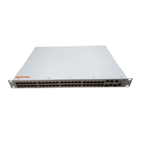
The console port, located on the chassis front panel, provides a
serial connection to the switch and is required when logging
into the switch for the first time. By default, this RJ-45
connector provides a DTE console connection.
1 Locate the console port on the front of
the switch.
2 Connect one end of an RJ-45-to-RJ-45
straight-through cable to the console port.
3 Connect the other end of an RJ-45-to-RJ-45 straight-
through cable to the supplied DB-9 to RJ-45 adapter.
4 Connect the adapter to the PC or terminal with the
default settings below.
Serial Connection Default Settings
The default settings for the serial connection are as follows:
Note. For information on modifying these settings, refer to
the OmniSwitch 6855 Series Hardware Users Guide.
Connections and Cabling
baud rate 9600
parity none
data bits (word size) 8
stop bits 1
 Loading...