Create and configure a coordinate system
Rockwell Automation Publication MOTION-UM002F-EN-P - February 2018 27
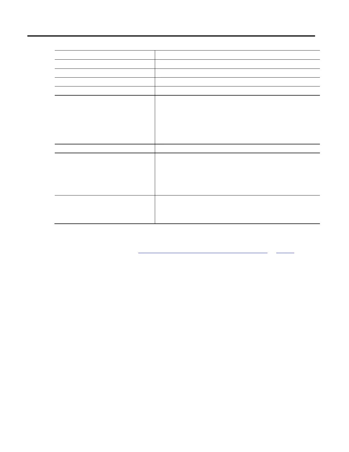
Parameter Description
Type Read-only. The robot geometry type selected on the General tab.
Coordinate Definition Read-only. The coordinate definition selected on the General tab.
Dimension Read-only. The dimension entered on the General tab.
Transform Dimension Read-only. The transform dimension entered on the General tab.
Coordination Units
Defines the units used for measuring and calculating motion-related values such as position and
velocity.
The coordination units do not need to be the same for each coordinate system. The units are relevant
to your application and maximize ease of use.
When the Coordination Units change, the second portion of the Coordination Ratio Units
automatically changes to reflect the new units.
Coordination Units is the default.
Axis Name Displays the name of the axis assigned to the coordinate system.
Conversion Ratio Defines the relationship of axis position units to coordination units for each axis.
For example, if the position units for an axis is in millimeters and the axis is associated with a
coordinate system whose units are in inches, then the conversion ratio for this axis/coordinate system
association is 25.4/1 and can be specified in the appropriate row of the Axis Grid.
Tip: The numerator can be entered as a float or an integer. The denominator must be entered as an
integer only.
Conversion Ratio Units Displays the axis position units to coordination units used.
The coordination units are defined in the Coordination Units parameter on this tab. The Axis Position
units are defined on the Units tab in the Axis Properties dialog box. These values are dynamically
updated when changes are made to either axis position units or coordination units.
See also
Coordination System Properties dialog box - Units tab on page 26
How do I open the Offsets tab?
1. In the Controller Organizer, expand the Motion Group folder, and
double-click the coordinate system.
2. On the Coordinate System Properties dialog box, click the Offsets tab.
Use the settings on the Offsets tab in the Coordinate System Properties dialog
box to define the end effector and base offset values for the robotic arm.
The Offset tab shows the views of a typical robotic arm based on the configuration
of the robot geometry type on the General tab. The type of offsets and the
number of available offsets is determined by the coordinate system and the
number of axes associated with the coordinate system.
When specifying the end effector and base offset values, be sure that the values are
calculated using the same measurement units as the linked Cartesian coordinate
system. For example, if the manufacturer specifies the robot offset using millimeter
units and you want to configure the robot using inches, then convert the
Coordinate System Properties
dialog box - Offsets tab
 Loading...

