Geometries with no orientation support
94 Rockwell Automation Publication MOTION-UM002F-EN-P - February 2018
Configure the Logix Designer application to control robots with varying reach
and payload capacities. The configuration parameter values for the robot include:
• Link lengths
• Base offsets
• End-effector offsets
The configuration parameter information is available from the robot
manufacturer.
Important: Verify that the values for the Link Lengths, Base Offsets, and End-Effector Offsets are entered in the Coordinate
System Properties dialog box using the same measurement units.
See also
Link Lengths for Delta Three-dimensional robot on page 94
Base Offsets for Delta Three-dimensional robot on page 95
End-Effector offsets for Delta Three-dimensional robot on page 95
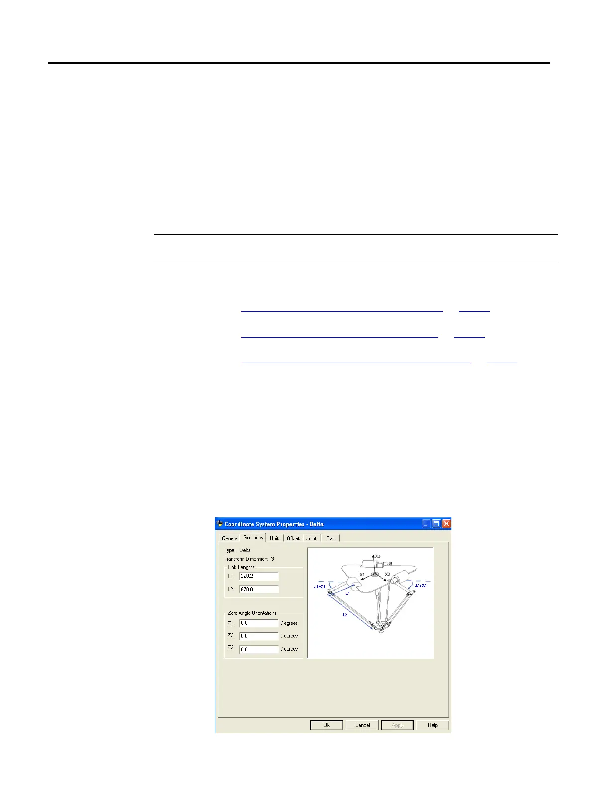
Link lengths are the rigid mechanical bodies attached at the rotational joints. The
three-dimensional Delta robot geometry has three link pairs made up of L1 and
L2. Each of the link pairs has the same dimensions.
• L1 - is the link attached to each actuated joint (J1, J2, and J3).
• L2 - is the parallel bar assembly attached to L1.
Enter the link lengths on the Geometry tab in the Coordinate System
Properties dialog box.
parameters for a Delta
Three-dimensional robot
Three-dimensional robot
 Loading...

