Geometries with no orientation support
Rockwell Automation Publication MOTION-UM002F-EN-P - February 2018 97
are actuated joints. The joints between links L1 and L2 and between L2 and the
base plate are unactuated joints.
Each joint is rotated independently to move the gripper to a programmed (X1,
X2) position. As each joint axis (J1 or J2 or J1 and J2) is rotated, the TCP of the
gripper moves correspondingly in the X1 or X2 direction or X1 and X2 direction.
Program the TCP to a (X1, X2) coordinate, then the Logix Designer application
uses internal vector dynamic calculations to compute the proper commands
needed for each joint to move the gripper linearly from the current (X1, X2)
position to the programmed (X1, X2) position.
The two joint axes (J1 and J2) of the robot are configured as linear axes.
To rotate the gripper, configure a third axis as a linear or rotary, independent axis.
See also
Establish the reference frame for a Delta Two-dimensional robot on page 97
Calibrate a Delta Two-dimensional robot on page 98
Identify the work envelope for a Delta Two-dimensional robot on page 98
Define configuration parameters for a Delta Two-dimensional robot on
page 99
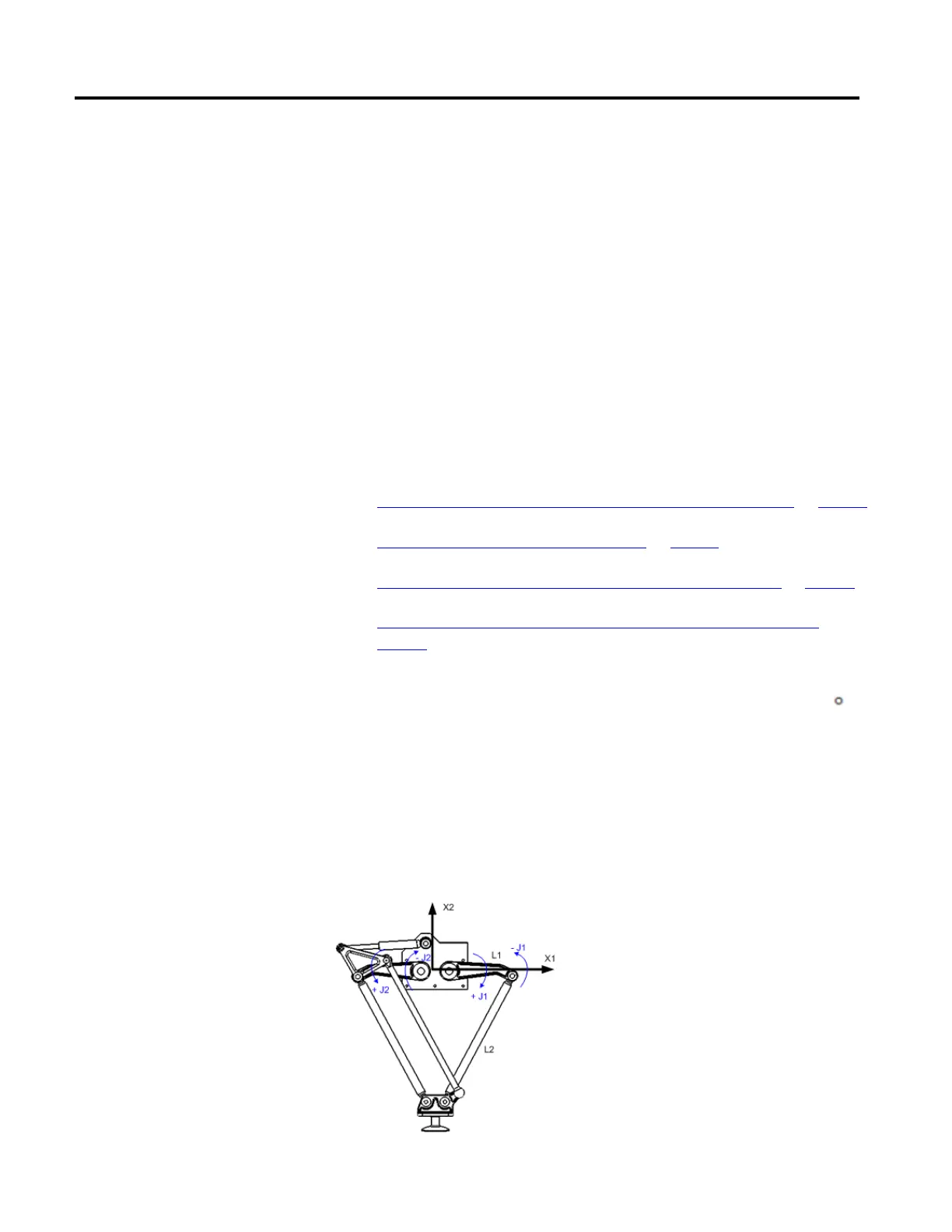
The reference frame for the two-dimensional Delta geometry is located at the
center of the fixed top plate. When the angles of joints J1 and J2 are both at 0
,
each of the two L1 links is along the X1 axis. One L1 link is pointing in the
positive X1 direction, the other in the negative X1 direction.
When the right-hand link L1 moves downward, joint J1 is assumed to be rotating
in the positive direction and when L1 moves upward, the J1 is assumed to be
moving in the negative direction. When the left-hand link L1 moves downward,
joint J2 is assumed to be rotating in the positive direction and when left-hand L1
moves upward, the J2 is assumed to be moving in the negative direction.
Establish the reference frame
for a Delta Two-dimensional
robot
 Loading...

