ALPINE R2-A75M/R2-A60F 68-44781Z33-B (EN/DE/FR/ES/IT/SE/RU/CS)ALPINE R2-A75M/R2-A60F 68-44781Z33-B (EN/DE/FR/ES/IT/SE/RU/CS)
6-EN
CONNECTION CHECK LIST
Please check your head unit for the conditions
listed below:
Remote Turn-On Lead
a. The head unit does not have a remote turn-on
or power antenna lead.
b. The head unit’s power antenna lead is activated
only when the radio is on (turns off in the tape
or CD Mode).
c. The head unit’s power antenna lead is logic level
output (+) 5 V, negative trigger (grounding
type), or cannot sustain (+) 12 V when
connected to other equipment in addition to
the vehicle’s power antenna.
If any of the above conditions exist, the remote
turn-on lead of your R2-A75M/R2-A60F must be
connected to a switched power source (ignition)
in the vehicle. Be sure to use a 3 A fuse as close
as possible to this ignition tap. Using this
connection method, the R2-A75M/R2-A60F will
turn on and stay on as long as the ignition
switch is on.
If this is objectionable, a SPST (Single Pole,
Single Throw) switch, in addition to the 3 A fuse
mentioned above, may be installed in-line on
the R2-A75M/R2-A60F turn-on lead. This switch
will then be used to turn on (and off) the
R2-A75M/R2-A60F. Therefore, the switch should
be mounted so that is accessible by the driver.
Make sure the switch is turned off when the
vehicle is not running. Otherwise, the amplifier
will remain on and drain the battery.
Cautions on wire lead connections
When using third-party wire cables (power supply
wire), use the supplied screws to simplify the
connection. Refer to the description below for the
proper procedure. If you are in doubt about how to
make this connection, consult your dealer.
1. Check the wire size.
• For details on the wires size to be used, refer to
the supplied “Cautions on Power Supply Wires
Connection” and “Cautions on Power Supply
Wires” (page 20), and then use the wire of
the specified size.
• If the wire gauge used is unknown, ask your
dealer.
2. Remove the insulation from the ends of the wire
leads by about 7 – 10 mm (9/32” – 13/32”).
Lead end side of
the product
Twist the tip of wire leads
7 – 10 mm
(9/32” – 13/32”)
NOTES:
• If length of the exposed wire is too short, a poor
connection may occur causing operation failure
or sound interruption.
• On the other hand, if the length is too long, an
electrical short-circuit may occur.
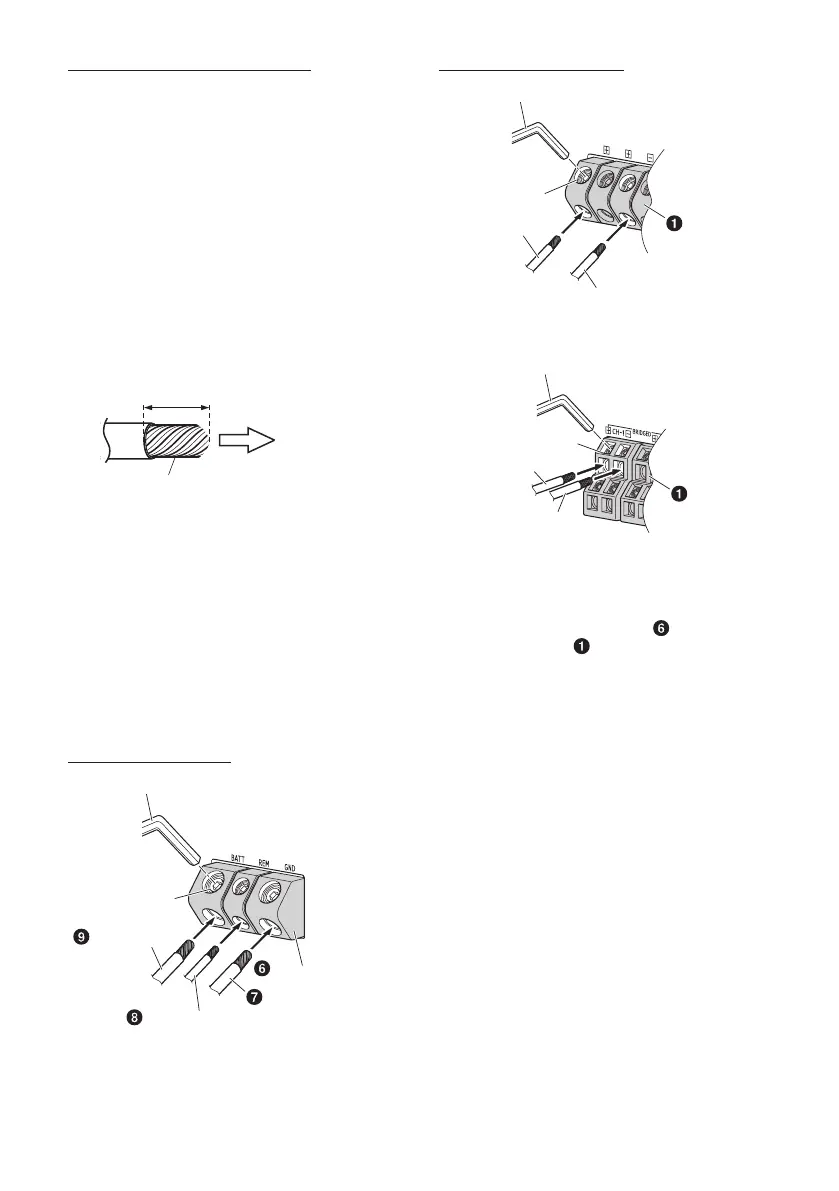
3. Tighten the hexagon hole screw with the
hexagon wrench (Large or Small) (included) to
secure the lead.
Before making this connection, use insulated
shrink tubing to cover any exposed wire
extending beyond the terminal.
Power Supply Terminal
Hexagon Wrench (included)
Battery Lead
Remote Turn-On Lead
Power Supply Terminal
Ground Lead
Hexagon hole
screw
Speaker Output Terminals
Hexagon Wrench (included)
Hexagon hole
screw
Speaker Output Lead (–)
Speaker Output
Lead (+)
Speaker Output
Terminals
R2-A75M
Hexagon Wrench (included)
Hexagon hole
screw
Speaker Output Lead (–)
Speaker Output
Lead (+)
Speaker Output
Terminals
R2-A60F
NOTES:
• Be sure to use the Hexagon hole screw attached
to the Power Supply Terminal ( ) or Speaker
Output Terminals ( ).
• For safety reasons, connect the battery leads last.
• To prevent disconnection of the leads or
dropping of the unit, do not use the cabling to
carry the unit.
 Loading...