PTAC
WIRELESS THERMOSTAT KIT (DSA01NM)
I
NSTALLATION INSTRUCTIONS
9/2015
IO-908A
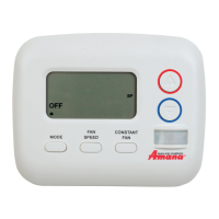
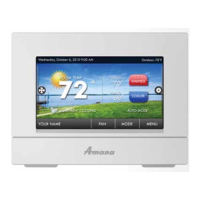
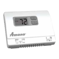
Thermostat
Due to policy of continued product improvement, the right is reserved to change specifications and design without notice.
Heat in
& Air Co ndit ion in
®
A
5151 San Felipe, Suite 500 • Houston, TX 77056
www. ama na-p ta c. co m
© Copyright 2015 Go odman Co mpany, L. P.
is a registered trademark of Maytag Corporation or its related companies and is used
under license to Goodman Company, L.P., Houston, TX, USA. All rights reserved.
ATTENTION INSTALLING PERSONNEL
As a professional installer you have an obligation to know the
product better than the customer. This includes all safety
precautions and related items.
Prior to actual installation, thoroughly familiarize yourself
with this Instruction Manual. Pay special attention to all
safety warnings. Often during installation or repair it is
possible to place yourself in a position which is more
hazardous than when the unit is in operation.
Remember, it is your responsibility to install the product
safely and to know it well enough to be able to instruct a
customer in its safe use.
Safety is a matter of common sense...a matter of thinking
before acting. Most dealers have a list of specific good
safety practices...follow them.
The precautions listed in this Installation Manual are in-
tended as supplemental to existing practices. However, if
there is a direct conflict between existing practices and the
content of this manual, the precautions listed here take
precedence.
RECOGN I ZE THI S SYM BOL
AS A SAFETY PRECAUTI ON.
The following installation instructions are for a typical
installation.
Please contact your PTAC salesperson for additional assis-
tance and explanation prior to ordering materials or cutting
openings.
1. ANTENNA INSTALLATION FOR DSA01NM KIT
An antenna must be installed on the digital PTAC to allow
operation of the DSA01NM remote RF thermostat.
PREPARATION
1. Disconnect power to the unit by unplugging the power
cord at the wall outlet or subbase, or disconnect power
at the fuse box or circuit breaker.
2. If the cabinet front is screwed to the chassis, remove
the 1/4” screw (or screws). See following figure.
Radio - Non Mesh
Antenna