Quick Start Guide
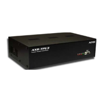
AXB-TPI/3 Touch Panel Interface 3
ATTENTION: READ THIS FIRST!
For more detailed installation, configuration, programming, and operating instructions,
refer to the AXB-TPI/3 Touch Panel Interface Instruction Manual available on-line at
www.amx.com.
Overview
The AXB-TPI/3 is a touch panel interface capable of using multiple (RGB and
consumer-type) inputs and of displaying its graphical user interface (GUI) output on
practically any type of monitor. The AXB-TPI/3 has three slots on the rear panel that
can contain any combination of three types of input modules:
• TP3-VID (composite video/S-video)
• TP3-RGB (RGB)
• TP3-VGA (VGA)
Installing the Input Modules (TP3-VID/RGB/VGA)
1. Discharge the static electricity from your body by touching a grounded metal
object and disconnect all connectors from the AXB-TPI/3.
2. Carefully unscrew (counter-clockwise) the two screws located at the rear of the
unit to remove each cover.
3. Gently insert the module into the brackets inside the card slot and slide the input
module into the enclosure until you feel it contact the slot connector.
4. Screw in (clockwise) the two thumbscrews to secure each module.
5. Repeat steps 2 and 3 to insert other input modules, if necessary.
6. When you are done installing the input modules, reconnect all connectors, and
apply power.
Preparing Captive Wires
You will need a wire stripper and flat-blade screwdriver to prepare and connect the
captive wires.
1. Strip 0.25 inch (6.35 mm) of insulation off all wires.
2. Insert each wire into the appropriate opening on the connector.
3. Tighten the screws to secure the wire in the connector. Do not tighten the
screws excessively; doing so may strip the threads and damage the connector.
Using External Power
To use the AXlink 2-pin connector for power transfer from the PSN6.5 power supply,
the incoming PWR and GND cable from the PSN6.5 must be connected to the
corresponding location on the green 2-pin rear panel connector (FIG. 2).
Using the Program and Mouse Ports (DB-9 RS-232 Connectors) for
Control and Communication.
The TPI has two DB-9 RS-232 connectors to support most standard serial touch
devices (serial mouse or touch panel) and RS-232 communication protocols (for PC
data transmission). There is a DB-9 connector on the front panel ( labeled PROGRAM
PORT) for communication with a PC, and one on the rear panel (labeled MOUSE
PORT) for connection to a touch device. The following table lists the (DB-9) RS-232
connector pinouts:
AXB-TPI/3 Specifications
Dimensions (HWD) • 3.47" x 13.75" x 8.38" (8.81 cm x 34.93 cm x 21.29 cm)
• With brackets installed for rack-mounting: 3.47" x 19.00" x 8.38"
(8.81 cm x 48.26 cm x 21.29 cm)
• With brackets rotated 45° for under/over/vertical surface
mounting: 3.85" x 19.00" x 8.38"
(9.78 cm x 48.2 cm x 21.29 cm)
Input Voltage 12 VDC
Current Consumption
(each input module requires
500 mA)
• 0 input module installed - 630 mA
• 1 input module installed - 1.13 A
• 2 input modules installed - 1.63 A
• 3 input modules installed - 2.13 A
Memory • Standard 9 MB (8 MB Flash)
Input/Output Resolution • 640x 480 @60 Hz to 1024 x 768 @ 60 Hz
Input and Output Refresh
Rates (per resolution)
Note: Input resolutions apply to RGB and VGA only
• 640 x 480 (VGA): 60 Hz, 72 Hz, 75 Hz, 85 Hz
• 800 x 600 (SVGA): 56 Hz, 60 Hz, 72 Hz, 75 Hz
• 1024 x 768 (XGA): 60 Hz
Front Components and
Connectors
• PROGRAM port (DB-9)
• LED Indicators - VGA (640x480 resolution), SVGA (800x600),
and XGA (1024 x768)
• AXlink LED - Green LED indicates AXlink communication
activity, power, and data status.
Rear Connectors • Mouse Port - RS-232 (DB-9) 9-pin serial port. The 9-pin serial
port is used to connect a pointer device, such as a serial mouse
or touch-screen overlay.
• VGA Monitor Out - HD-15 15-pin connector for VGA monitor
output.
• RGB Monitor Out - 5 BNC output connectors (from left to right)
red (R), green (G), blue (B), horizontal sync (H), and vertical
sync (V) for RGB monitor output.
• AXlink connector - 4-pin AXlink data/power bus (captive-wire)
connector
• PWR connector - 2-pin 12 VDC power supply (captive-wire)
connector
Input Module Slots/Outputs • Three slots on rear panel can be equipped with any combination
of input modules (S-Video/Composite, VGA, and RGB). The
TPI/3 handles multiple input resolutions and refresh rates.
Input Modules • TP3-VID - Use the TP3-VID input module in any input slot to
connect video sources, such as VCRs and DVDs. The TP3-VID
module has one composite video connector and one S-video
input connector.
• TP3-RGB - Use the TP3-RGB input module in any input slot to
connect RGB-type sources. The TP3-RGB module uses 5 BNC
connectors for R, G, B, H and V.
• TP3-VGA - Use the TP3-VGA input module to connect VGA-
type sources (common for PCs). The TP3-VGA module uses a
HD-15 connector.
Included Accessories • Two rack-mount ears and a package of rack screws
• One 4-pin AXlink connector
• One 2-pin PWR connector
Optional Accessories • PSN6.5 power supply (12 VDC)
• Input module (TP3-VID, TP3-RGB, and TP3-VGA)
FIG. 1 Inserting an input module (TP3-VID, TP3-RGB or TP3-VGA)
FIG. 2 12 VDC Power Connector
(DB-9) RS-232 Connector Pinouts
Pin Signal Function
1N/ANot used
2 RXD Receive data
3 TXD Transmit data
4N/ANot used
5 GND Signal ground
6N/ANot used
7N/ANot used
8N/ANot used
9N/ANot used
Thumbscrews
rear panel
PSN6.5
+ (PWR)
- (GND)
2-pin captive-wire
power connector
+12 VDC power supply
9
8
7
6
5
4
3
2
1
9
8
7
6
Female
Male
(Mouse or PC)
(TPI)