QUICK START GUIDE
AXB-VOL3 3-Channel Volume Controller
Overview
The AXB-VOL3 (FG5756) controls three audio volume channels. Each line-level channel,
opto-isolated from system ground, can be configured for balanced or unbalanced line
operation. It is programmable for 128 steps of audio level, audio mute, variable ramp
speed and level presets.
Specif ications
Installation
Setting the DEVICE DIP Switch
Note: Use the DIPSwitch 2.0 application available for free download from AMX to quickly
figure out DIP Switch settings for all types of DIP Switches.
Set the device number on DEVICE DIP switch, located on the front of the AXB-VOL3. The
device can be 1 of the 255 devices in an Axcess control system. The device number
must match the device assignment in the Axcess program. Device numbers are
assigned into the following three segments:
• Cards 1 through 95
• Boxes 96 through 127
• Panels 128 through 255
Set the device number by setting the device DIP switches. The device number is the
total of all of the switches in the ON position, and take effect by cycling the power.
Wiring
Preparing and Connecting Captive Wires
1. Strip 0.25 inch of wire insulation off all wires.
2. Insert each wire into the appropriate opening on the connector according to the
wiring diagrams and connector types described in this section.
3. Tighten the screws to secure the wires. Do not tighten the screws excessively;
doing so may strip the threads and damage the connector.
Wiring Guidelines
The interface requires a 12 VDC power to operate properly. The interface uses a PS2.8
power supply. The Central Controller supplies power via the AxLink cable or external 12
VDC power supply.
The maximum wiring distance between the Central Controller and interface is
determined by power consumption, supplied voltage, and the wire gauge used for the
cable.
The table below lists wire sizes and maximum lengths allowable between the VOL3 and
Central Controller. The maximum wiring lengths for using
AxLink power are based on a minimum of 13.5 volts available at the Central Controller’s
power supply.
AxLink Connector
Install the AxLink data/power bus wiring as shown in FIG. 2.
Volume Channels 1 - 3 Connectors
Volume channels 1 - 3 can be wired for unbalanced or balanced line operation, as
shown in FIG. 3.
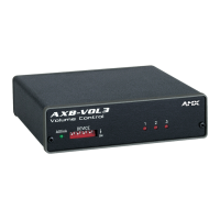
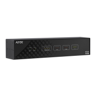
FIG. 1
AXB-VOL3
AXB-VOL3 SPECIF ICATIONS
Three Line-level Audio Control Channels:
Line operation: Balanced or unbalanced
Audio ground: Audio ground opto-isolated from system ground.
Nominal input level: -10 to +4 dBm.
Max. input/output level: +16 dBm.
Volume level resolution: 128 volume level steps (+
.5 dB per step).
Attenuation: 72 dB at full attenuation (mute).
Total Harmonic Distortion: THD = <.008%
Frequency Response 20 Hz to 20 kHz +/- 1 dB
Front Panel Components
AxLink LED AxLink LED (green and blinks to indicate AxLink
communication activity and power:
• Full-Off indicates no power is being received or the
controller is not functioning properly.
• One blink per second indicates power is active and AxLink
communication is functioning.
• Full-On indicates there is no AxLink control or activity, but
power is On.
Device DIP Switch An 8-position DIP switch used to set the AxLink device
number for the AXB-VOL3.
Channel LEDs Red channel LEDs 1 - 3. The LEDs individually light indicating
a change in channel levels.
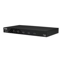
Rear Panel Components
AxLink connector 4-pin, captive wire connector, receives power and
information via the AxLink and AxLink Central Controller.
Volume Channel
connectors
6-pin, captive wire connectors that control audio level, audio
mute, variable ramp speed and level presets of up to 3
devices.
Enclosure Metal with black matte finish
Dimensions (HWD) 1.51" x 5.55" x 5.45" (3.84 cm x 14.10 cm x 13.84 cm)
Weight 1.1 lb (0.499 kg)
AxLink Power 12 VDC @ 230 mA
FIG. 2 AXB-VOL3 REAR PANEL
GND
AXP
AXM
PWR
OUT
OUT
GND
IN
IN
GND
IN
OUT
OUT
GND
GND
IN
OUT
IN
GND
OUT
IN
GND
AXlink VOL CHAN 3 VOL CHAN 2 VOL CHAN 1
Volume Channel
connectors
AxLink connector
DEVICE DIP SWITCH SETTINGS
Position 12345678
Value 1248163264128
WIRING GUIDELINES AT 230 MA
Wire Size Maximum Wiring Length
18 AWG 510.31 feet (155.54 m)
20 AWG 371.29 feet (113.17 m)
22 AWG 201.29 feet (61.35 m)
24 AWG 126.88 feet (38.67 m)
FIG. 3 AXLINK DATA/POWER CONNECTIONS
FIG. 4 VOLUME CHANNELS 1 - 3 CONNECTOR WIRING DIAGRAMS
PWR
AXP
AXM
GND
PWR
AXP
AXM
GND
AXB-VOL3
Control
system
GND
IN-
IN+
GND
OUT-
OUT+
Unbalanced IN
Jumper IN- to GND
Unbalanced OUT
GND
IN-
IN+
GND
OUT-
OUT+
Balance
IN
Balance
OUT
Optional 600 ohm resistor can be added for impedance matching, if required