© 2016 Harman. All rights reserved. SmartScale, NetLinx, Enova, AMX, AV FOR AN IT WORLD, and HARMAN, and their respective logos are
registered trademarks of HARMAN. Oracle, Java and any other company or brand name referenced may be trademarks/registered trademarks of
their respective companies.
AMX does not assume responsibility for errors or omissions. AMX also reserves the right to alter specifications without prior notice at any time.
The AMX Warranty and Return Policy and related documents can be viewed/downloaded at www.amx.com.
3000 RESEARCH DRIVE, RICHARDSON, TX 75082 AMX.com | 800.222.0193 | 469.624.8000 | +1.469.624.7400 | fax 469.624.7153
AMX (UK) LTD, AMX by HARMAN - Unit C, Auster Road, Clifton Moor, York, YO30 4GD United Kingdom • +44 1904-343-100 • www.amx.com/eu/
Last Revised: 6/8/2016
2. Plug the other ends of the power cords into power sources.
3. Turn on the power strip and wait until the system status indicator flashes green.
4. Check the Indicator LEDs on front and rear of the enclosure; see table below.
5. For Enova DGX 800/1600/3200 systems with ASB Boards – Attach HSSI cable
from SMA port on ASB Input Board to SMA port on ASB Output Board.
6. For systems with boards that require modules – Apply power to the modules.
7. Apply power to the source and destination devices.
If indicator lights do not respond with a normal display as stated in the table below,
check power connections and see the troubleshooting information in the manual before
contacting technical support.
Executing a Test Switch with Control Panel
The Control Panel (standard on all enclosures) is used for controlling system switches
and attributes. Use Control Panel (or System Configuration interface) to execute test
switch.
Control Panel Keys and Dial
• Function Key – Press for start of the Function menu anytime during operation.
• Control Dial – Turn to scroll through the Function menu (starts with Change for
switching). After scrolling past the last item, the menu loops back to the first item.
• Select Key – Press to enter selections.
• Take Ke y – Press to complete an operation.
• Cancel Key – Press to cancel an incomplete operation.
To disconnect factory default switch and execute test switch via Control Panel:
1. From the Function menu, locate Disconnect by scrolling with the Control Dial and
then press the Select Key.
2. Press Input Key 1; press the Take Key.
3. The default switch of “1 to all” is disconnected.
4. Press the Function Key; press the Select Key to select Change.
5. The available Input and Output Keys turn blue.
6. Press Input Key 1. Input Key 1 flashes white.
7. Press Output Key 1. Output Key 1 illuminates white.
8. Press the Take Key to execute the switch. Both keys turn blue.
When done, attach remaining sources and destinations. For products that require
transmitters or receivers, install appropriate modules between boards/devices.
Establishing a LAN Connection
The Enova DGX Switcher has an integrated NetLinx Central Control Processor with the
server connection via the LAN 100/1000 port on the right-hand side of the CPU.
IMPORTANT: (1) Enova DGX Switchers use DHCP by default. (2) Do not
connect the
LAN 100/1000 port on Enova DGX Switcher directly to a PC. It will not
work.
Cable Requirements for the LAN Connection
Connect the LAN 100/1000 port on the Enova DGX Switcher directly to a LAN
(network) with an RJ-45 cable (crossover or straight-through; port automatically
adjusts). A DHCP capable server must be in the network.
To connect an Enova DGX Switcher to a LAN:
1. If the system is not already powered, apply power according to the directions
starting in the lower right-hand column on the first page.
2. Insert one end of an RJ-45 link cable into the LAN 100/1000 port.
3. Connect the other end of the RJ-45 link cable to a LAN hub or switch.
The network will automatically assign a DHCP IP address.
4. Check the indicator LEDs on the LAN 100/1000 port (FIG. 5 right).
NOTE: The Program port can be used to establish a connection from the integrated
Master to a PC for NetLinx Studio control.
IMPORTANT: The ICS LAN port on the left of the CPU is for communication via Telnet of
endpoint devices connected to the integrated Master in Auto-setup Mode. The ICS LAN
allows the DGX to provide Private IP addresses to all connected endpoints while only
consuming a single IP address on the Public LAN. Please note, however, that the ICS LAN
port serves DHCP addresses to any connected device. If the ICS LAN is inadvertently
connected to the Public LAN, devices also on the Public LAN may experience DHCP
address conflicts.
System Setup via the System Conf iguration Interface
The System Configuration interface (onboard web pages) provides simplified setup and
configuration of inputs, outputs, and endpoints, and complete switching, as well as
status functionality.
IMPORTANT: The System Configuration interface requires a browser running HTML5.
Minimum web browser requirements are: Google Chrome 31, Internet Explorer 10,
Firefox 25, or Safari 7. User experience may differ due to browser support for HTML5.
TIP: After the enclosure is connected to a network, the system’s IP address can be
obtained via the Control Panel by accessing the Setup Options / Master Info / IP Address
screen. The IP address can be entered in a web browser to open the System
Configuration interface.
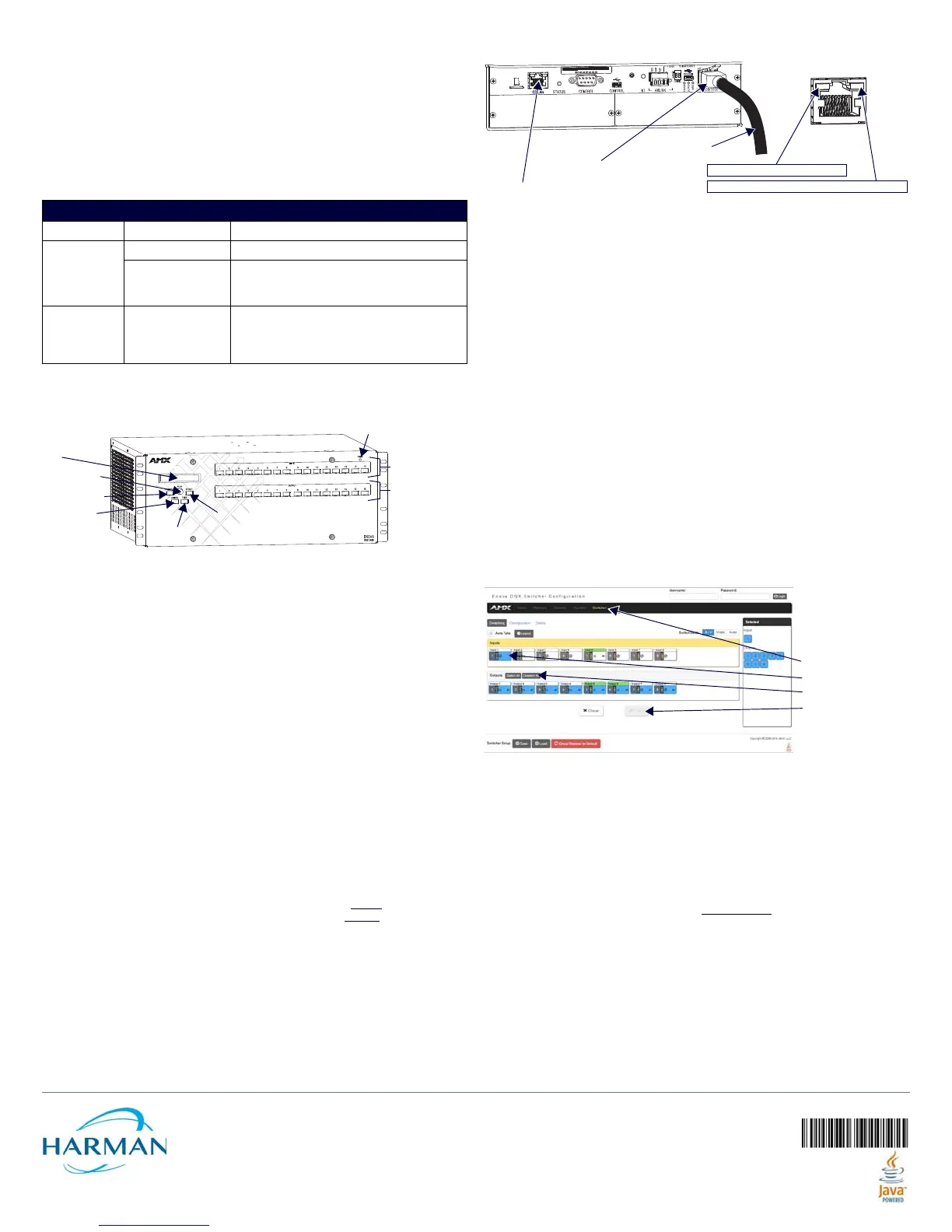
To disconnect the factory default switch and execute a test switch via the System
Conf iguration interface:
1. From the System Configuration Home page menu, open Switcher/Switching.
NOTE: The default Username is “administrator” and default Password is “password.”
2. In the Inputs section, click Input 1.
3. In Outputs section, click the Deselect All button.
4. Click the Take button. The default switch of “1 to all” is disconnected.
5. Click Input 1, Output 2, and then click Take button to execute test switch.
When done, attach remaining sources/destinations. For products requiring TXs/RXs,
install modules between boards/devices. For details on system setup of the Master via
the System Configuration interface, see the WebConsole & Programming Guide –
NX-Series Controllers. For Input/Output configuration (scaling, EDID, DSP, etc.) via the
System Configuration interface, see the switcher’s Hardware Reference Manual.
Additional Information Covered in Hardware Reference Manual
For information on the following, see the Hardware Reference Manual - Enova DGX 800/
1600/3200/6400 Digital Media Switchers at www.amx.com
.
• Input and Output Board specifications and signal support
• NetLinx programming and firmware upgrades
• System Configuration interface – full switching/configuration/status information
• Setup for complete power redundancy with redundant power supplies
• Adding or replacing boards
Reference Documents
• Hardware Reference Manual – DXLink Twisted Pair 4K Transmitters and Receivers
• Hardware Reference Manual – DXLink Twisted Pair Transmitters/Receiver
• Hardware Reference Manual – DXLink Fiber Transmitters and Receivers
• “Cabling for Success with DXLink” (on DXLink Twisted Pair product pages)
• WebConsole & Programming Guide – NX-Series Controllers
INDICATOR LEDS – NORMAL DISPLAY ON POWER UP
Front Panel Power – power status Green (when all power supplies are working)
Power Supplies
(DC is Tri-color)
AC power Green
•DC power
•Temperature
•Fault status
Green (amber = over temperature; red = fault
state)
CPU Status – system
status
• Solid amber during boot load (10 sec)
• Solid green during app load (1-4 minutes,
depending on system configuration)
• Flashing green when ready
FIG. 4 FRONT VIEW WITH CONTROL PANEL (ENOVA DGX 1600 SHOWN)
Function Key
Control Dial
Select Key
LCD
Cancel Key
Take Key
Output Keys
Input Keys
Power Indicator
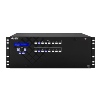
FIG. 5 CPU WITH LAN 100/1000 PORT (RJ-45) AND INDICATOR LEDS
LAN 100/1000 port (RJ-45)
To L AN
ICS LAN port (RJ-45)
SPD LED (yellow): Receiving/transmitting LAN data
L/A LED (green): Active connection
ICS LAN and LAN 100/1000 LEDs
Click Deselect All
Click Input 1
Click Take
Select Switcher menu
 Loading...