Installation Guide
ZigBee Installation Tips
Overview
The ZigBee protocol provides a standards-based wireless network solution
that is simple to develop and deploy, and affords robust security, high data
reliability, and product interoperability. When properly deployed, a ZigBee
network will provide “Wireless Control that Simply Works”.
For a successful ZigBee installation, it is critical to understand that the
ZigBee wireless protocol is influenced by the same environmental factors
that affect other wireless systems. Interference from radio emitters, various
electronic devices, and blockage due to solid objects may slow or stop
communication between devices on the ZigBee network.
This paper is intended to assist with setting up a wireless network with the
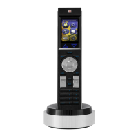
best possible communication between ZigBee devices (such as the Mio
R-4) and ZigBee access points (APs) - ZXR-ZGW Gateways and ZXR-ZRP
Repeaters.
As shown in FIG. 1 below, the Mio Modero
®
R-4 #1 (on the left) has clear
access to the ZigBee Repeater “A” in the high elevation, but may have
problems with connection to the Repeater “B” in the low elevation.
The R-4 #2 faces potential signal blockage from furniture in the way of the
Repeater “B”. The R-4 #2 will only send an unimpeded signal to Repeater
“B” if it is elevated above the furniture.
• Mio R-4 #1 may have problems with connection if the user moves
closer to the microwave or the light ballast.
• Both Mio R-4s face interference when reaching a Repeater on the
opposite side of the room due to microwave oven and light ballast in
the center.
Although these are examples of sources of potential interference and signal
blockage, the presence of these factors may or may not result in noticeable
performance degradation.
Environmental issues must be faced with every ZigBee network installation.
Wireless Antenna Radiation Patterns
The antennas used for both the Gateways and Repeaters provide a
uniform, 360-degree radiation pattern (FIG. 2). This radiation pattern should
be taken into account when designing a ZigBee wireless network, in order
to assure that a Gateway or Repeater in a particular location has coverage
in both the vertical and horizontal axes.
• The Horizontal pattern indicates the shape and range of coverage of
the ZigBee signal, as it radiates from the antenna horizontally. Use this
chart to understand what the area of coverage will be, around the
ZigBee AP.
• The Vertical pattern indicates the shape and range of coverage of the
ZigBee signal, as it radiates from the antenna vertically. Use this chart
to understand what the area of coverage will be above and below the
ZigBee AP. This chart is particularly useful in multi-story installations
where you need an AP to span floors.
Note that the Vertical pattern indicates two dead zones around the 0°
and 180° positions.
Note: The radiation patterns may vary slightly depending upon the channel
being used.
Performing a Full Site Survey
For the best possible results, you should always start by performing a full
site survey to fully understand the wireless network and RF environment in
which your ZigBee network will operate.
Site Survey Tools
A site survey is typically performed using a laptop PC equipped with a
wireless adapter card and mapping software. A laptop PC allows you to
move around within the installation area to scan for access points and
possible “dead spots” in the RF environment.
There are many free wireless network mapping software applications
available, including “NetStumbler” and “Chanalyzer”. These tools provide a
visual overview of the local wireless network, and indicate the number of
wireless access points in the area as well as the amount of wireless
network traffic on any given RF channel or frequency. This is the most basic
information that you’ll need to optimize access point (AP) placement.
Performing the Site Survey
To perform an effective site survey for AMX ZigBee devices, consider
placing ZigBee Gateways/Repeaters in various locations in the installation
area that represent the overall area of the installation environment.
If possible, run the site survey with all other electronic devices in the
general area (plasma screens, DVD players, microwave ovens, lighting
ballasts, cordless phones, non-ZigBee access points, etc.) turned ON to
determine possible interference when these devices are operating. Many of
these devices may produce interference as far away as 10 feet (3.4 m)
away during operation.
When performing the site survey, note the following:
• The number of wireless access points (WAPs) in the area, and the
location of each.
• The signal strength for each WAP.
• The channels/frequencies that are already being used.
• Dead-spots in the area (weak or no RF signals detected)
This information enables you to determine the best placement and
configuration of your ZigBee network:
• Avoid placing ZigBee Gateways/Repeaters in close proximity
(< 5 feet / 1.52 m) to other WAPs.
• Avoid using heavily trafficked channels.
• Avoid dead spots created by interference, reflection or blockage.
Target RSSI and SNR values
Two key values presented by mapping software are RSSI (Received Signal
Strength Indication) and SNR (Signal to Noise Ratio). The RSSI and SNR
reported for each AP in the wireless network tell you how strong the signal
from each AP is, usually updated in real-time.
As a general rule, good target values to have for reliable wireless
connections used in a NetLinx control system are:
• An RSSI value between -55 and -78 dBm
• An SNR value greater than or equal to 18 dBm
FIG. 1 Recommended placement of ZigBee Gateways/Repeaters.
FIG. 2 Wireless antenna radiation patterns - horizontal and vertical positions
Vertical patternHorizontal pattern
DEAD ZONE
DEAD ZONE


 Loading...