Do you have a question about the AMX NetLinx Integrated Controllers NI-700/900 and is the answer not in the manual?
| Model | NI-700/NI-900 |
|---|---|
| CPU | 32-bit RISC |
| Memory | 64 MB SDRAM |
| Ethernet Ports | 1 |
| RS-232 Ports | 4 |
| Serial Ports | 4 |
| IR Ports | 4 |
| Relay Ports | 4 |
| Power Supply | 12 VDC |
| Operating Temperature | 32° to 104° F (0° to 40° C) |
| Control Ports | IR, Relay, I/O |
Details the warranty terms and limitations for AMX products.
Lists the key features of the NI-700 and NI-900 controllers.
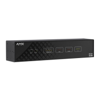
Details the front and rear panel components and connectors of the NI-700.
Detailed description of NI-700 front panel components like ports and LEDs.
Details the rear panel RS-232/422/485 connectors for the NI-700.
Specific details on IR RX, Digital I/O, IR/Serial, AXlink, Ethernet, and Power ports.
Covers operating conditions, included accessories, and other AMX equipment.
Details NI-700 port assignments and on-board memory specifications.
Lists the key features of the NI-700 and NI-900 controllers.
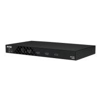
Details the front panel LEDs, ports, and configuration switches of the NI-900.
Detailed description of NI-900 front panel components like ports and LEDs.
Details the rear panel RS-232/422/485 connector for the NI-900.
Specific details on IR RX, Digital I/O, IR/Serial, AXlink, and Ethernet ports.
Covers operating conditions, included accessories, and other AMX equipment.
Details NI-900 port assignments.
Details the memory configurations for different NI-900 model variations.
Information about the TimeKeeper component in NI controllers.
Lists other relevant documentation for the NetLinx controllers.
Explains the D:P:S notation for device identification in NetLinx programming.
Steps for mounting the controller into a standard 19-inch equipment rack.
How to set the baud rate using the DIP switch on the controller.
How to set the baud rate using the DIP switch on the controller.
How to set the PRD mode using the DIP switch on the controller.
Instructions on how to set the DIP switches for baud rate and PRD mode.
How to connect the controller's program port to a PC for programming.
Explains the meaning of different LED blink patterns on the front panel.
Lists port assignments for NI-700 and NI-900 controllers.
Describes the AXlink port functionality and its status LED indicators.
Provides general guidelines for wiring the integrated controllers.
Tables showing maximum wiring lengths based on wire gauge.
Steps for preparing wires for connection to the controller terminals.
Instructions for wiring the 12 VDC power connection using a mini-Phoenix connector.
Wiring diagram for connecting devices using the 4-pin mini-Phoenix connector.
Wiring for the 4-pin mini-Phoenix connector using an external power source.
Pinout and wiring specifications for the DB9 serial ports.
Detailed wiring specifications for RS-232, RS-422, and RS-485 device ports.
How to connect IR receivers to the IRX-RX port on the controllers.
Describes the connections and wiring for the I/O ports.
How to connect IR or serial devices to the IR/Serial ports.
Pinouts, signals, and pairing for the Ethernet RJ-45 connector.
Explanation of the status and speed LEDs on the Ethernet port.
Lists and describes the standard Ethernet ports used by the controller.