© 2015 Harman. All rights reserved. Radia Eclipse, AMX, AV FOR AN IT WORLD, HARMAN, and their respective logos are registered trademarks of
HARMAN. Oracle, Java and any other company or brand name referenced may be trademarks/registered trademarks of their respective companies.
AMX does not assume responsibility for errors or omissions. AMX also reserves the right to alter specifications without prior notice at any time.
The AMX Warranty and Return Policy and related documents can be viewed/downloaded at www.amx.com.
3000 RESEARCH DRIVE, RICHARDSON, TX 75082 AMX.com | 800.222.0193 | 469.624.8000 | +1.469.624.7400 | fax 469.624.7153
AMX (UK) LTD, AMX by HARMAN - Unit C, Auster Road, Clifton Moor, York, YO30 4GD United Kingdom • +44 1904-343-100 • www.amx.com/eu/
Last Revised: 11/09/2015
Low-Voltage Connections
The low-voltage area in the AMX Lighting controllers contain connections and DIP
switches for AxLink and dry closures. On the controller cards, low-voltage power for the
board is supplied either by line power, optional auxiliary power supply (RDA-PSM), or
the +12 VDC pin on the AxLink connector.
WARNING: Disconnect the main power to the AMX Lighting controller at the breaker box
before rewiring the low voltage connections.
Setting AxLink Address Numbers
Set the AxLink address number (1-255) for the RE-DM6. This number must match the
number in your Axcess program.
Note: By turning all switches off, all circuits will go to 100 percent so that the installer
can test the high-voltage connections without having connections to a control system.
Connecting AxLink
Connect the 4-pin captive-wire AxLink connector from the RE-DM6 to the Central
Controller for AxLink control of the dimming system (FIG. 5).
Dry Closure Connections
Dry contact closures from other equipment can be connected to the Radia Eclipse
dimmer module to provide direct manual control of lighting loads (FIG. 6).
Each dry contact closure has two pins: ground and contact. To activate each dry
closure, connect the ground and contact.
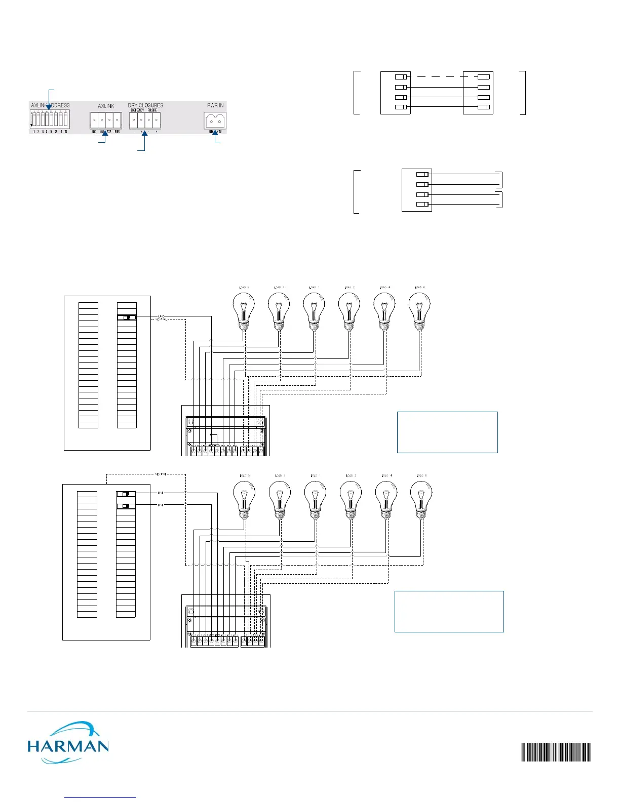
FIG. 4
LOW-VOLTAGE CONNECTIONS AND DIP SWITCHES
AxLink address DIP switch
Dry contact closures
Auxiliary power IN
AxLink connector
FIG. 5 CONNECTING AXLINK
FIG. 6 DRY CLOSURE CONNECTIONS
Central
RE-DM6
Controller
PWR
AXP
AXM
GND
PWR
AXP
AXM
GND
RE-DM6
FAILSAFE
GND
EMERGENCY
GND
Failsafe switch
Alarm system
FIG. 7 EXAMPLE A
FIG. 8 EXAMPLE B
Example A
Single Input
Single-phase, six load
120 or 240 VAC 1Ø
Lighting Application Drawings
Example B
Dual Input
Single-phase, six load
120, 120/240, 240 VAC 1Ø
 Loading...