17
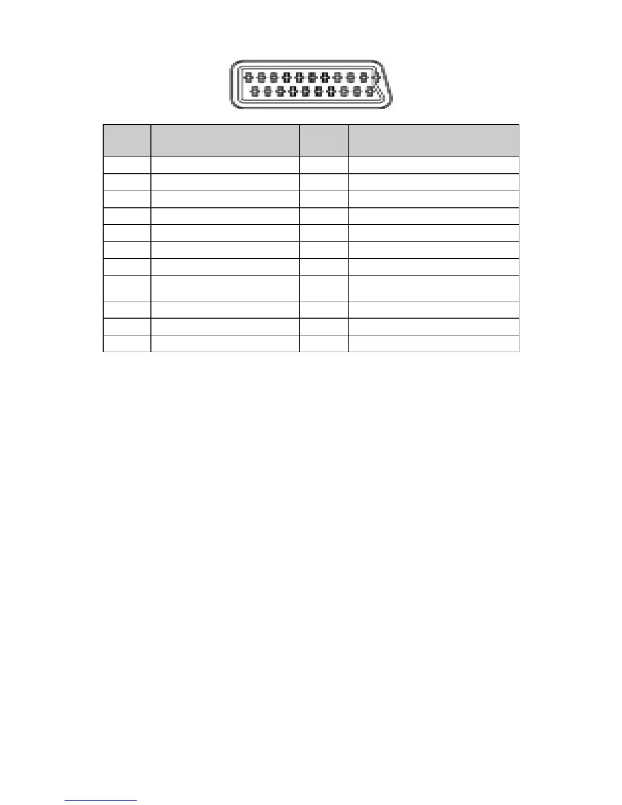
Full Scart Connector Pin Assignments
Pin No. Description Pin No. Description
1
Audio Output Right
12
N.C.
2
Audio Input Right
13
GND(Red)
3
Audio Output Left
14
GND(Blanking)
4
GND(Audio)
15
Red Input
5
GND(Blue)
16
RGB Switching Control
6
Audio Input Left
17
GND(Video Input & Output)
7
Blue Input
18
GND(RGB Switching Control)
8
Switch Signal Input (Fast
Blanking)
19
Video Output(Composite)
9
GND(Green)
20
Video Input(Composite)
10
N.C.
21
Common Ground
11
Green Input
3.3 Video/Audio Signals
·TV RF input system -Aerial or cable should support PAL/SECAM/DVB-T
·TV RF input level -10mV (80dBuV) typical, 30dBuV ~ 100dBuV receiving capability, terminated with input
impedance of 75Ω.
·CVBS input -1000mVpp (including 300 mV sync level), terminated with input impedance of 75Ω.
·Component video input -Y: 1000mVpp (include sync), PbPr: 700mVpp terminated With Input impedance of 75Ω.
Support 480i/p, 576i/p, 720p, 1080i at 50Hz or 60Hz refresh rate
·Audio input -Sensitivity 500mV (rms). For rated power, the amplifier should be able to handle input
signal up to 2.0V, input impedance > 10KΩ.
·SCART input / output -Full SCART, includes RGB in, CVBS (audio L/R) in/ (TV out). Half SCART includes
S-Video in, CVBS (audio L/R) in/ (TV out).
·HDMI (High Definition Multimedia Interface)
-Support 480i /480p, 576i/576p, 720p, 1080i format with HDCP
-Digital interface with 4 channels TMDS signal
·CI Slot -PCMCIA card 5V input.
·PC VGA input -700 mV input level, TTL level sync, RGB in, 75Ω impedance.
·PC Audio input -500 mVrms input level, impedance > 10 kΩ.
·SPDIF output -Level: +/- 0.5V Square Wave.
·Amplifier output -3W+/-10%
·Speaker -8Ω
 Loading...