EP2C621D12 WS
Quick Installation Guide
www.asrockrack.com
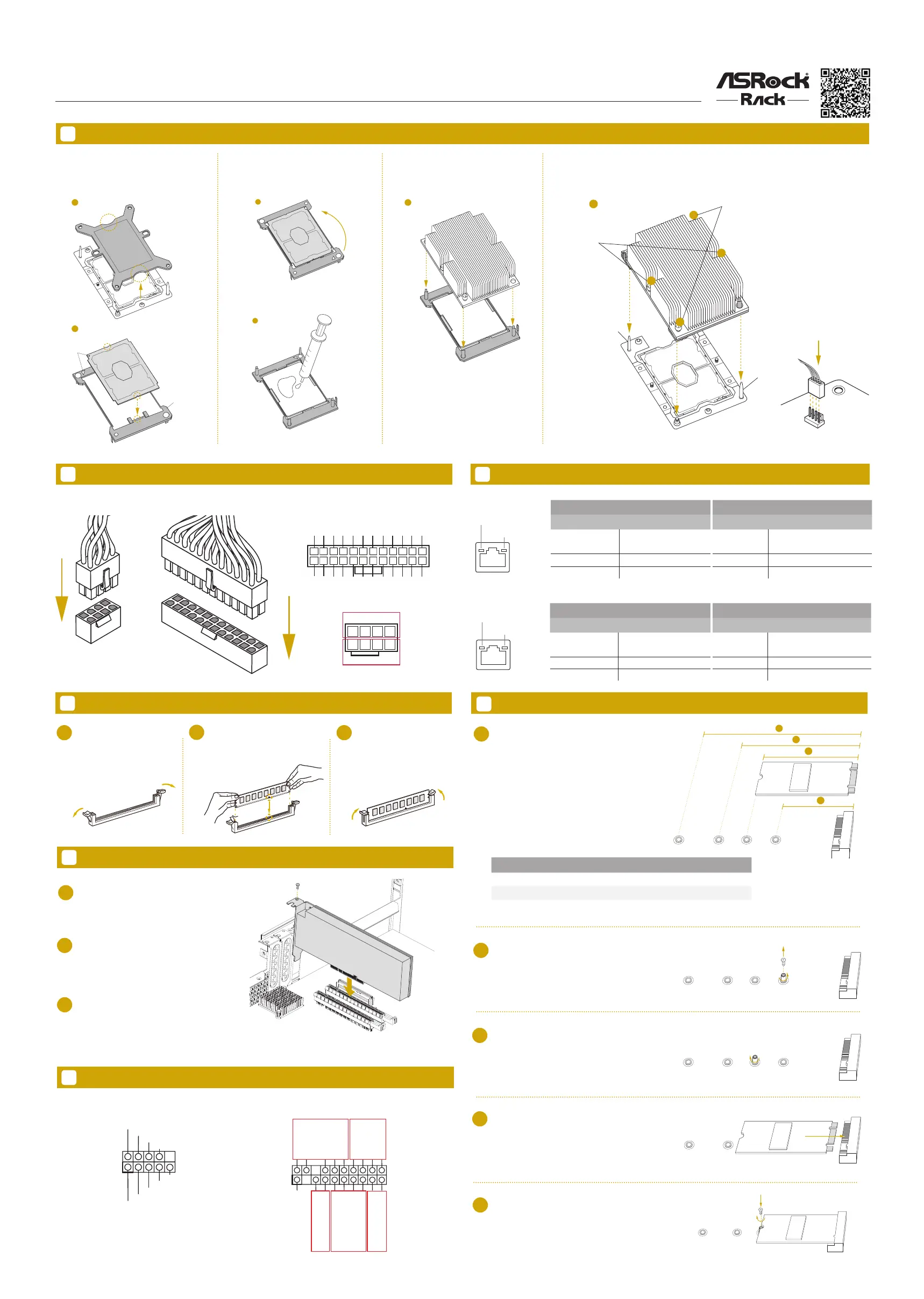
Activity / Link LED Speed LED
Status Description Status Description
O No Link O 10M bps connection or no
link
Blinking Yellow Data Activity Yel low 100M bps connection
On Link Green 1G bps connection
7 LAN Port LED Indications
5
6
Remove the CPU socket cover. Align and
install the processor on the carrier.
Carefully ip the carrier assembly. Apply
a thermal paste .
en install the heatsink to the carrier
assembly and make sure the arrow is
located in the correct direction.
Install the heatsink. Tighten the screws in a sequential order (6-1>6-2>6-3>6-4). When
dissembling the heatsink, loosen the screws in reverse order (6-4>6-3>6-2>6-1). Connect
the CPU fan to the CPU FAN connector.
Install the Power Cables
9
Install the PCIE Card
1
Remove the bracket facing the slot that
you intend to use. Keep the screw for
later use.
2
Align the card connector with the
slot and press firmly until the card is
completely seated on the slot.
Fasten the card to the chassis with the
screw.
3
IPMI LAN Port
ACT/LINK LED
SPEED LED
LAN Port
Install the Processor and Heatsink
3V
3V
GND
GND
5V
5V
GND
PWROK_PS
5VSB
12V
12V
3V
121
13
24
3V
-12V
GND
PSON#
GND
GND
GND
5V
5V
5V
GND
N/A
We recommend using the CPU Installation tool to avoid CPU pin-bent problem.
1
2
PIN1
CPU Carrier
3
4
180
o
5
6
Tighten the two
Middle Nuts to
12 IN.LB.
Two turns at a time.
Tighten the two
Corner Plunger
to 12 IN.LB.
Tw
o turns at a time.
6-1
6-2
6-3
6-4
Guide Pin
Guide Pin
*Images shown are for illustrative purposes only and may dier depending on model.
8
Install the Memory
1
2
3
Unlock a DIMM slot by
pressing the module clips
outward.
Insert the memory module. Lock the clips.
11
M.2_SSD (NGFF) Module Installation
System Panel Auxiliary Panel
10
Headers
GND
RESET#
PWRBTN#
PLED-
PLED+
GND
HDLED-
HDLED+
1
GND
4
8
1
5
12V
GND
LAN Port
1
2
3
Find the corresponding nut location to be used.
Move the stando based on the module type and
length.
Peel o the yellow protective lm on the nut. Hand
tighten the stando into the desired location.
Align and gently insert the M.2 module into the
slot.
Tighten the screw with a screwdriver to secure
the module into place. Please do not overtighten
the screw.
4
5
1
2
3
4
NUT1NUT2NUT3NUT4
NUT1NUT2NUT3NUT4
NUT1NUT2NUT3NUT4
NUT1NUT2NUT3NUT4
NUT1NUT2NUT3NUT4
No. 1 2 3 4
Nut Location NUT30 NUT42 NUT60 NUT80
PCB Length 3cm 4.2cm 6cm 8cm
Module Type Type 2230 Ty pe 2242 Type2260 Type 2280
GND
SMB_CLK
SMB_Alert
CASEOPEN#
1
SMB_DATA
+3VSB
LAN1_LINK
LED_PWR
LAN2_LINK
LED_PWR
+5VSB
GND
GND
LOCATORLED1+
LOCATORLED1-
LOCATORBTN#
System Fault LED+
System Fault LED-
A
B
CD
E
ACT/LINK LED
SPEED LED
LAN Port
Activity / Link LED Speed LED
Status Description Status Description
O No Link O 10Mbps connection or no
link
Blinking Yellow Data Activity Orange 100Mbps connection
On Link Green 1Gbps connection
 Loading...