Do you have a question about the ASROCK PHANTOM GAMING B760M PG LIGHTNING and is the answer not in the manual?
| Form Factor | Micro ATX |
|---|---|
| Chipset | Intel B760 |
| CPU Socket | LGA 1700 |
| Memory Slots | 4 x DDR5 DIMM |
| Maximum Memory | 128GB |
| PCIe Slots | 1 x PCIe 5.0 x16, 1 x PCIe 4.0 x16 (x4 mode), 1 x PCIe 3.0 x1 |
| M.2 Slots | 2 x M.2 |
| USB Ports (Rear) | 4 x USB 3.2 Gen1, 2 x USB 2.0 |
| Video Outputs | 1 x HDMI, 1 x DisplayPort |
| SATA Ports | 4 x SATA3 |
| USB Ports (Internal) | 1 x USB 3.2 Gen1, 2 x USB 2.0 |
| Audio | Realtek ALC897 |
| LAN | Realtek RTL8125BG 2.5Gbps |
Lists items included with the motherboard, such as manuals and cables.
Details platform, CPU, Chipset, Memory, and Expansion Slot specifications.
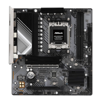
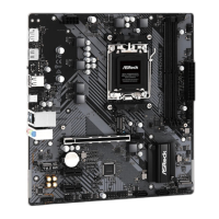
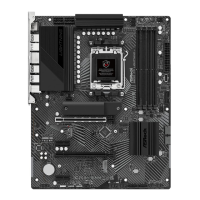
Diagram showing the physical layout of motherboard components and connectors.
Details the rear panel connectors and their functions for the WiFi model.
Illustrates the internal data flow and connections between CPU, Chipset, and peripherals.
Describes the features and specifications of the integrated Wi-Fi and Bluetooth module.
Important safety and handling guidelines before installing components.
Step-by-step guide for correctly installing the CPU into the motherboard socket.
Instructions for mounting the CPU cooler and connecting its fan.
Explains how to install DDR4 RAM modules into the DIMM slots and configurations.
Guide for connecting front panel wires (power, reset, LEDs) to the motherboard header.
Instructions on how to install the rear I/O shield into the computer case.
Steps for physically mounting the motherboard inside the computer chassis.
Guide on connecting SATA data and power cables to storage devices.
Instructions for installing a graphics card into the PCIe slot.
Shows how to connect external peripherals like monitor, keyboard, mouse, and speakers.
Details how to connect the main ATX and CPU power supply cables to the motherboard.
Steps to power on the computer for the first time after installation.
Explains the function and usage of jumpers, specifically the Clear CMOS jumper.
Details the System Panel Header for connecting front panel buttons and LEDs.
Describes the connection for chassis intrusion detection and system speaker.
Explains the placement and function of SATA3 connectors for storage devices.
Information on the two USB 2.0 headers and their port capabilities.
Details the USB 3.2 Gen1 header for connecting two front panel USB ports.
Instructions for connecting the front panel audio jacks to the motherboard.
Explains the four 4-pin connectors for chassis and water pump fans.
Information on CPU fan headers for cooling system components.
Details the 24-pin ATX and 8-pin ATX 12V power connectors on the motherboard.
Describes the SPI TPM header for enhanced security features.
Information on connecting a Thunderbolt add-in card (AIC) to the motherboard.
Explains the function of the Post Status Checker LEDs for diagnosing boot issues.
Guide for installing the M.2 WiFi/BT module.
Instructions for installing an M.2 SSD into the M2_1 socket.
Instructions for installing M.2 SSDs into the M2_2 and M2_3 sockets.