ASUS P5GC 2-25
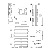
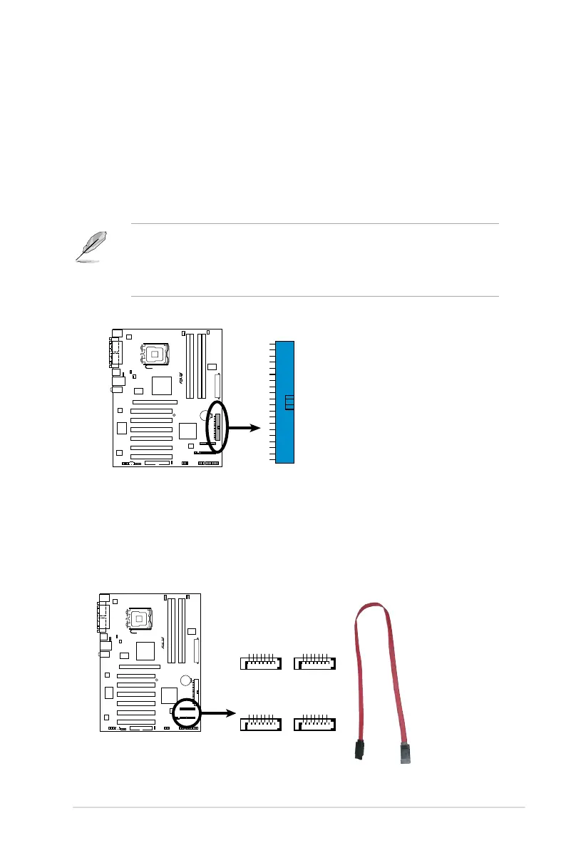
3. Serial ATA connectors (7-pin SATA1 [red], SATA2 [red], SATA3 [black],
SATA4 [black])
These connectors are for the Serial ATA signal cables for Serial ATA hard disk
drives.
P5GC
SATA Connectors
P5GC
GND
RSATA_TXP1
RSATA_TXN1
GND
RSATA_RXP1
RSATA_RXN1
GND
GND
RSATA_TXP2
RSATA_TXN2
GND
RSATA_RXP2
RSATA_RXN2
GND
SATA1
SATA2
GND
RSATA_TXP3
RSATA_TXN3
GND
RSATA_RXP3
RSATA_RXN3
GND
GND
RSATA_TXP4
RSATA_TXN4
GND
RSATA_RXP4
RSATA_RXN4
GND
SATA3
SATA4
2. ICH7R Primary IDE connector (40-1 pin PRI_IDE)
This connector is for an Ultra DMA 100/66/33 signal cable. The Ultra
DMA 100/66/33 signal cable has three connectors: a blue connector for the
primary IDE connector on the motherboard, a black connector for an Ultra
DMA 100/66 IDE slave device (optical drive/hard disk drive), and a gray
connector for an Ultra DMA 100/66/33 IDE master device (hard disk drive).
If you install two hard disk drives, you must congure the second drive
as a slave device by setting its jumper accordingly. Refer to the hard disk
documentation for the jumper settings.
• Pin 20 on the IDE connector is removed to match the covered hole on the
Ultra DMA cable connector. This prevents incorrect insertion when you
connect the IDE cable.
• Use the 80-conductor IDE cable for Ultra DMA 100/66/33 IDE devices.
P5GC
IDE Connector
P5GC
PRI_IDE
 Loading...