 Loading...
Do you have a question about the Asus P5LP-LE and is the answer not in the manual?
| Manufacturer | Asus |
|---|---|
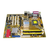
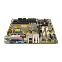
| Form Factor | Micro ATX |
| Chipset | Intel 945G |
| CPU Socket | LGA 775 |
| Memory Type | DDR2 |
| Memory Slots | 4 |
| Maximum Memory Supported | 4 GB |
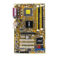
| PCIe x16 Slots | 1 |
| PCI Slots | 2 |
| PCIe x1 Slots | 1 |
| SATA Ports | 4 |
| IDE Ports | 1 |
| LAN | Realtek RTL8111B |
| Onboard Video | Intel GMA 950 |
| Audio | Realtek ALC888 |
| Ethernet | Gigabit |
| USB Ports | 8 |
Detailed steps for installing the CPU into the motherboard's LGA775 socket.
Information on enabling and using Intel Hyper-Threading Technology with the CPU.
Guidelines for installing DDR2 DIMMs and recommended memory configurations.
Procedure for correctly installing a DDR2 DIMM module into a socket.
Procedure for safely removing a DDR2 DIMM module from a socket.
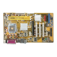
Step-by-step instructions for installing an expansion card into a slot.
Steps to configure installed expansion cards via BIOS settings and drivers.
How to use the CLRTC jumper to clear CMOS and system passwords.
How to use the CLPWD jumper to reset a forgotten BIOS password.
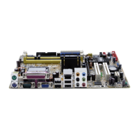
Identification and function of all ports on the motherboard's rear panel.
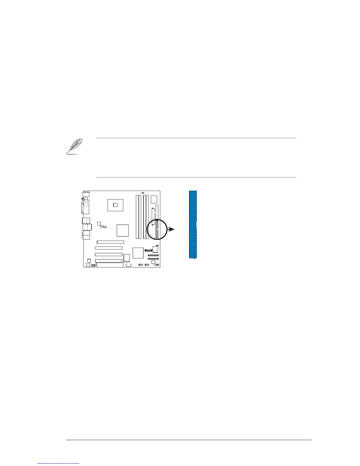
Identification and function of internal connectors for system components.