Phono (RCA)
Connector
To Source Output
Two Core Screened Cable
3 Pin Male XLR
Connector
To Monitor Input
1
2
3
Hot
Screen
Return
Two Core Screened Cable
3 Pin Male XLR
Connector
3 Pin Female XLR
Connector
To Monitor Input
Hot
Return
Screen
To Source Output
1
2
3
1
2
3
5 . S i g n a l C a b l e O p t i o n s
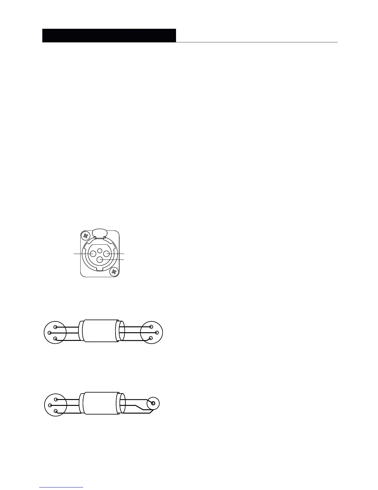
Balanced cable configuration is the preferred option,
however unbalanced connection is possible. Diagrams 2 and
3 illustrate the signal cable connections required for
each option. Balanced (XLR to XLR) connection offers
lower noise and better immunity to “hum” pick-up.
Unbalanced (XLR to Phono or Two pole Jack)
connection carries risk of hum caused by multiple
signal earths. Hum problems resulting from unbalanced
connection may be reduced by making ONE of the
following modifications to the signal cable
connections: If the driving preamplifier (or desk) is
“double insulated” (i.e. has no mains earth),
disconnect the signal cable screen at the RCA Phono
plug end. Alternatively, disconnect the signal cable
screen at the XLR end.This second option will make
the source the reference signal earth.
6 . O p e r a t i o n
Diagram 4 illustrate the connection and controland 5 panels for the Amplifiers
used in the active monitors. Each feature is described below.
5.1
Mains Inlet:
The supplied mains power lead (appropriate to the local
territory) should be connected here. Ensure that the mains voltage specified on
the panel corresponds with the local supply voltage.
5.2 Power Switch:
Switches on the monitor When. switched on the indicator
on the switch will illuminate.
5.3 Fuseholder:
Should a monitor fail to switch on when the power switch is
operated the fuse should be inspected. Lift out the fuseholder cover using a
small flat-blade screwdriver th efuse and inspect it for damage. Ifremove
required a replacement fuse should be fitted, . It should be stressed however that
fuses most most electrical fault. If this is theoften fail only because of a serious
case then simply replacing the in another fuse failure. Thefuse will only result
monitor should be returned to ATC if a second fuse fails.
5.4
Input Socket:The audio signal cable should be connected here. Balanced or
or unbalanced cables may be used (See Section 3).
5.5
Bass Boost:
Provides up to 6dB of gain (3dB for the SCM25 and SCM45)
in the region of 40Hz. Use a small flat blade screwdriver to access the control.
Adds more warmth and energy to the lower frequencies in music,
at the expense of accurate transient reproduction.
Note:
Adjusting the bass boost without the ability to recalibrate may leave a
pair of monitors unmatched.
5.6
LevelTrim : Provides access to an internal control that enables
adjustment of input sensitivity. Use a small flat blade screwdriver to access the
control. As supplied, monitors are calibrated to an input sensitivity of 1V.
Note:
Adjusting the sensitivity without the ability to recalibrate will leave a pair
of monitors unmatched.
Due to the nature of the electronics in ATC active loudspeakers it is quite normal
for a sound to be heard from the speaker when the power is applied or
disconnected. The noise heard will not damage the speaker and is quite normal.
Although ATC uses the highest-grade components, a different noise may be heard
from each speaker due to slight tolarance variations in the amplifier components.
4
Active monitors
7 . C o n n e c t i o n
Two cable connections are required for each monitor: one for mains power and one
for the audio signal. The mains cable is specifically supplied to comply with local
statutory safety approvals and alternatives should not be substituted. If you intend to
use your monitors in an alternative territory please contact ATC for advice.The mains
connection must always be earthed.
The signal cable and plug (not necessarily supplied) should be of a good quality and
XLR terminated. Poor cable and plug quality will compromise the performance of
your monitors.The signal input pin configuration is illustrated in Diagram 1.
Diagram 1 - input connection pins
Pin 1, Screen
Pin 2, Signal (hot)
Pin 3, Signal (return)
2 1
3
PUSH
Diagram 2 - balanced cable
Diagram 3 - unbalanced cable
SCM 50/100/ 15025/45/ 110/
I n s t a l l a t i o n
 Loading...