1
PAGE
Repair Instructions No.181.03/98
PHE 6 H / PHE 6 S
Special Tools
Required
■
Torx screwdriver TX 30 4932 319 998
■
Forcing disks 4931 599 018
■
Adjustment tool for carbon brushes 9170 302 270
■
Pulling-off device 9170 314 440
■
Tool for dis-/assembly of the spindle (PHE 6 H) 9170 302 260
Important!
■
Before beginning the maintenance work, perform an initial check with a high voltage test according
to VDE (see chapter Electrical and Mechanical Test Instructions).
■
Before all repair work, pull the power plug from the socket!
■
Before disassembly, the machine must be connected to the RTR-READER (maintenance measuring in-
strument) in order to check for a possible maintenance interval.
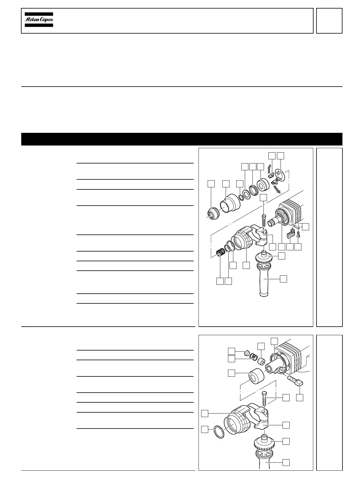
Disassembly
PHE 6 S:
Dismantling the
tool reception
1
Remove the auxiliary handle (G) com-
pletely with the clamping ring (F).
2
Push back the rubber cover (2) and re-
move the end cover cap (1).
3
Remove the spring ring (3).
4
Remove the stop (4), the rubber stop (5)
and the retainer (6).
5
Depress the retention plate (8) against re-
silience - the latches (7) are relieved. Un-
screw the latches (7) and remove them
(see illustration 1).
6
Remove the retention plate (8), the
spring (L) and the washer (K).
7
Take out the restrictor (J).
8
Remove the cone (H).
9
Loosen the bearing bolt (9). Keep the ten-
sion and carefully remove the clamping
ring (E).
10
Peel off the connecting ring (D).
11
Unscrew both screws (B). Slightly lift the
switch lever (C) and pull out the retaining
strap (A). Remove the switch lever (C).
PHE 6 H:
Dismantling the
tool reception
1
Remove the auxiliary handle (C) com-
pletely with the clamping ring ring (B).
2
Remove the dust guard cap (3).
3
Expel the latch (8) from the nosepiece with
aid of a mandrel.
4
Remove the latch (5), the spring (4) and
the distance sleeve (6).
5
Take out the restrictor (1).
6
Pull off the cone (2).
7
Loosen the bearing bolt (9). Keep the ten-
sion and carefully remove the strap (A).
8
Peel off the connecting ring (7).
9
1
654
32
7 8
C B
A
D
F
G
HJ
KL
E
1
8
4
3
2
9
A
5
B
6
C
7
 Loading...