Refrigerant circuit
Compressor (4) delivers hot, high-pressure refrigerant gas which flows through condenser (6) where most
of the refrigerant condenses.
Next, the liquid refrigerant flows through dryer/filter (7) to capillary tube (8). The refrigerant leaves the
capillary tube at evaporating pressure.
The refrigerant enters evaporator (2) where it withdraws heat from the compressed air by further
evaporation at constant pressure. The heated refrigerant leaves the evaporator and is sucked in again by the
compressor.
The condenser (6) pressure must be kept as constant as possible to obtain stable operation. Fan control
switch (P) therefore stops and starts the condenser cooling fan. If, under partial or no load, the evaporator
(2) pressure drops to approximately 2.25 bar(e) (32.63 psig), the hot gas bypass valve (5) opens and hot,
high-pressure gas is fed to the evaporator circuit to prevent the evaporator pressure from dropping any
further.
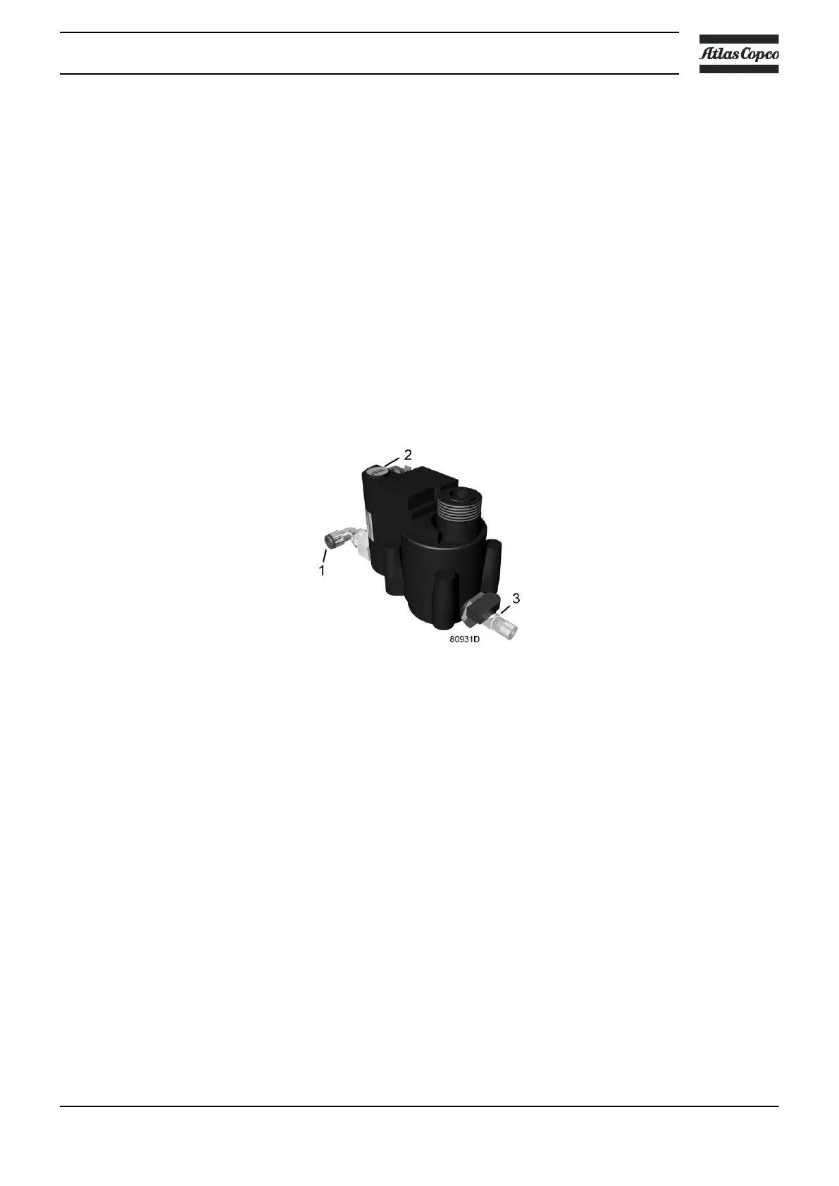
Electronic condensate drain
The dryer is equipped with an electronic condensate drain. The condensate, separated by the condensate
trap, accumulates inside the drain. Once the condensate reaches a certain level, it is discharged through the
drain outlet (1).
The condensate can also be drained by pressing the test button (2).
The drain filter can be cleaned by opening the manual drain valve (3), see section Preventive Maintenance
schedule.
Instruction book
2920 7110 11 17
 Loading...