SRTT-B User Guide
GENERAL
• Next Calibration date
• Source of Calibration
The stationary reaction torque transducers are designed for testing
wrenches, click wrenches or for tightening tool where rotary action
is not desired during measurement. In case of Shut-Off tool test a
joint simulator as accessories is required.
MODELS
Model
Capacity
(Nm)
Drive Ordering No.
SRTT-B 0.5 – 13 0.5
½” square
8059 0946 03
SRTT-B 2 – 13 2
½” square
8059 0946 09
SRTT-B 5 – 13 5
½” square
8059 0946 15
SRTT-B 25 – 36 25
36mm hex
8059 0946 28
SRTT-B 50 – 36 50
36mm hex
8059 0946 36
SRTT-B 100 – 36 100
36mm hex
8059 0946 45
SRTT-B 250 – 36 250
36mm hex
8059 0946 54
SRTT-B 500 – 50 500
50mm hex
8059 0946 63
SRTT-B 1000 – 50 1000
50mm hex
8059 0946 75
SRTT-B 2000 – 50 2000
50mm hex
8059 0946 84
The SRTT-B is the new generation of Atlas Copco Stationary
Reaction Torque Transducer with improved durability thanks to its
new mechanical design. The new patented system to fix the joint
simulator on top avoids any possible errors due to the play between
those two devices.
A complete line of accessories and Mechanical Joint Simulator
makes you able to test Shut-Off tools or wrenches with square drive
output.A built in memory stores identification and calibration data
for automatic reading from the measurement instrument.
TECHNICAL
• Torque Measurement Range: 0.5 ÷ 2000 Nm
• Static accuracy: ± 0.25% of rated max. transducer capacity
OPERATIONS
• Overload capacity: 125% of rated max. transducer capacity
Select the correct size of SRTT-B, which is at least the maximum
torque capacity of the tool to be tested.
• Temperature stability: 0.1% of capacity / °C
• Bridge resistance: 350 ohm
Before use be sure that the SRTT-B is well fixed to a structure
which can withstand to the torque you are going to apply. The
transducer can be fastened by means of the bolts or clamped
between the two flat surfaces on the side of its base.
• Operation humidity: 10-75% non condensing
• Operating temperature: 5 to 40°C
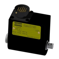
The transducer comes with Atlas Copco BLM calibration
certificate.
See the mechanical drawing for dimensions.
The calibration data is marked on the transducer label (when
installing the item always use this data, not the nominal values)
When SRTT-B 25 Nm or higher is used without a mechanical joint
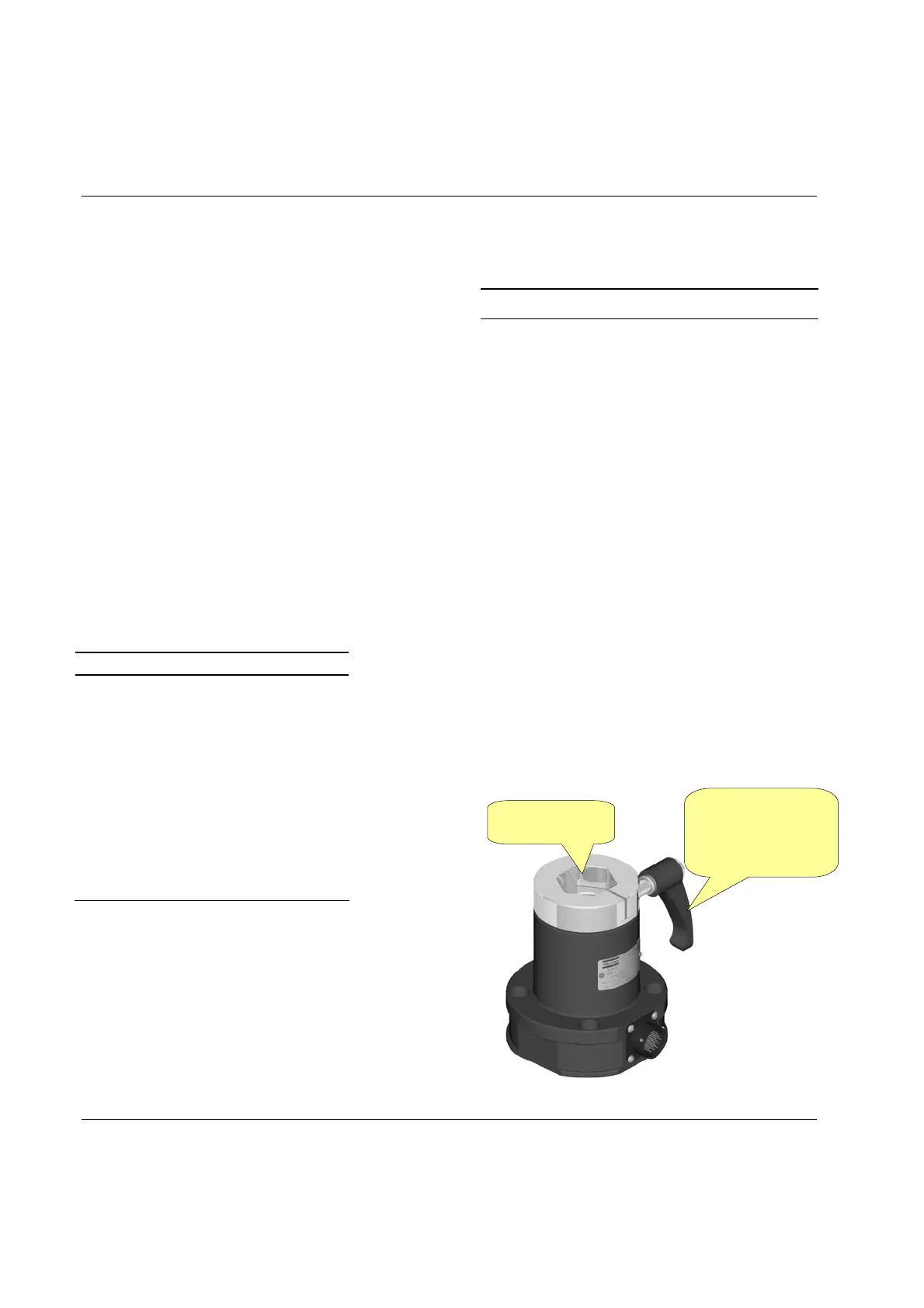
simulator, install an appropriate adapter in the hexagonal socket.
Lock the tool on the SRTT-B tightening the lever on the SRTT-B.
CONNECTOR PIN OUT
Connect the transducer 19 pin cable between the transducer and the
measurement instrument.
Pin Function
A Excitation +5VDC
B Excitation –5VDC
C Signal +
D Signal –
E –
F –
G Eeprom Clock
H
J Eeprom data
K-L-
M-N
–
P Ground (angle and eeprom)
R –
S –
T + 8/12VDC eeprom power supply
U-V –
If you use an ACTA instrument the calibration data will be loaded
automatically and no manual entering of the value is required.
If you use another measuring instrument the transducer shunt
calibration value and the angle pulses must be entered manually.
The shunt calibration value is marked on the transducer, the bridge
impedance is 350 Ohm and a 43,575 Ohm resistor is necessary.
Operate the tool in a normal way direct into the transducer socket.
Avoid side forces which may affect the measuring result.
Insert adapter or
joint simulator
Lock before starting the
test (the lever is present
only in models with
hexagon drive)
TRANSDUCER BUILT IN MEMORY
The built in memory consist in a eeprom, which stores the
following data:
• Identification
• Calibration (Nm)
• Full scale value (% of cal. Value)
• Sensitivity (2mV/V)
• Pulses / rev
• Serial Number.
• Date of latest calibration
4 (8) 9836 5232 01 Edition 2.0
 Loading...