41/83
IT EN FR DE ES
6
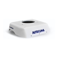
Position the cooling unit so that the outgoing and intake compartments correspond precisely with the openings cut
into the vehicle’s roof. Secure it to the roof using M8 screws (not supplied) (g. 06 - 07).
8
Along with the electrical wiring, you will also nd an led light I which signals, if turned on, a problem with the
pressure switch or with the pressure of the refrigerant inside the circuit.
The led light can be installed directly on the air diuser (g. 08 - 09 - 10) or in a remote position (connect using
the specic connection wiring provided K).
If the led light is installed in a remote position, it is necessary to install a lead (not supplied) between the led
light and the cable bundle located under the base of the unit.
9
Connect the J power supply wiring to the (+/-) poles of the terminal block on the air conditioner and bring the other
end of the wiring to the (+/-) poles of the alternator or battery.
The fuse (100A @ 12V / 60A @ 24V) must be located near the alternator or battery (wiring diagram).
10
After having completed all electrical connections, proceed with the assembly of the air diuser D.
Carefully join the diuser to the roof panel (taking care to join the incoming and outgoing air openings with the
relative openings on the diuser) and secure it with the supplied 6 self-threading screws JJ and washers KK (g.
07 / 11).
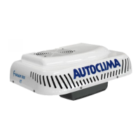
11 Secure the external shell with screws AA - BB - CC - DD - EE - FF (g. 06 - 07) and check correct operation.
7
Complete all electrical wire connections following the instructions of the electrical wiring diagram.
Install the supplied ventilation speed control F (or the electronic control unit E) , directly on the air diuser (g.
08) or in a remote position.
If the selector (or the electronic control unit) is installed on the diuser, connect it directly to the cable bundle
located under the base of the unit using the specic connection wiring (L / M) provided.
If the selector (or the electronic control unit) is installed in a remote position, it is necessary to install a lead (not
supplied; can be purchased separately as code 60654299) between the selector and the cable bundle located
under the base of the unit.
For "only cooling" version with manual controls, place the control plate H and relative knob G in order to complete
the installation of the selector (g. 08a / 10a).
 Loading...