4.Use and Operation Instruction
12
4.3. Startup & shutdown
Keep long press of " "for 0.5 s
to enter ON/OFF interface
When there is no operation
within 15 minutes, it will
display with full screen off
When the unit is started under the control of wire controller, if using the emergency switch to
shut down, the wire controller will display as follows:
Operations are the same as under ON/OFF main interface.
4.4. Mode switch
Under the main interface, Short press" "to switch the unit among heating " ", cooling " "
and automatic mode " ".
When there is no operation
within 1 minute, it will display
with half screen off
Notes:
Startup & shutdown operation can only be conducted in the main interface.
When it displays with half screen off or full screen off, click any key for returning to ON/OFF
main interface.
13
4.Use and Operation Instruction
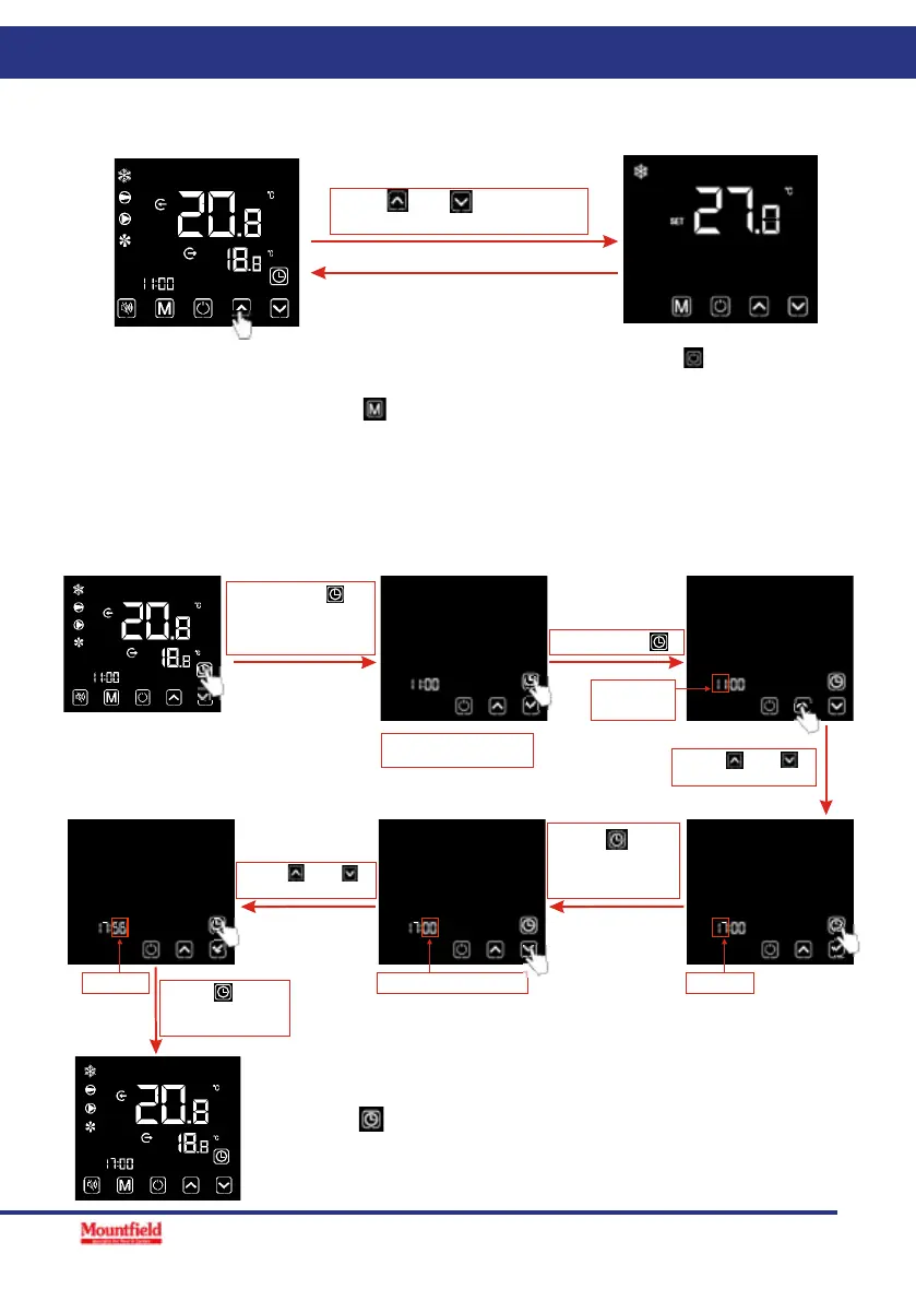
Notes: Under the temperature setting interface, if short press " ", the system will return to
the main interface without any changes saved; If there is no operation for 5 s or short press
" ", the current mode will be saved, and return to the main interface.
Short press" " for to switch the
mode circularly, after no operation
for 2s, the current mode will be saved.
Cooling mode
Automatic mode
2). When the unit is under the defrosting state, the defrosting symbol is on,with the display
interface as follows:
Notes:
1).After completing the defrosting, the unit will be automatically switched to the heating/
automatic mode (keeping consistent with the mode before defrosting).
During the defrosting, mode switch is available. And when switching the mode, the unit won t
work under a new mode until defrosting is completed.
Heating mode
Operation descriptions:
1). Mode switch operation can only be conducted in the main interface.
4.5. Temperature setting
Press " " or " " for increasing
or decreasing target temperature.
4.5. Temperature setting
Notes: Under the temperature setting interface, if short press
4.Use and Operation Instruction
2.1 Key function instruction
4.1.Interface display
Designation
Mute key
Mode key
On-off key
Up key
Down key
Clock key
Under the heating mode or heating mode under the
automatic mode, the mute key operation is effective and
used to enter and exit the mute mode with one click.
4.2.Key and icon function instruction
Key symbols
It is used to switch the unit mode, temperature setting,
and parameter setting.
It is used to carry out startup & shutdown, cancel current
operation,and return to the last level of operation.
It is used to page up, and increase variable value.
It is used to page down, and decrease variable value.
It is used as user clock, and to carry out timing setting.
Function
10
11
2.2.Icon function instruction
4.Use and Operation Instruction
Icon symbol
Designa tion
Function
Cooling
symbol
Heating
symbol
Automatic
symbol
Defrosting
symbol
Compressor
symbol
Water pump
symbol
Fan symbol
Mute symbol
Timing symbol
Water outlet
symbol
Water inlet
symbol
Locking key
symbol
Fault symbol
Wireless signal
symbol
Degrees Celsius
symbo
l
Degrees Fahrenheit
symbol
Setting symbol
Second symbol
Minute symbol
Hour symbol
Pressure
symbol
Flow symbol
It will display during cooling (there is no limit to startup &
shutdown, and it is optional when the unit is cooling-only
unit or heating-and-cooling unit).
It will display during heating (there is no limit to startup &
shutdown, and it is optional when the unit is heating-only
unit or heating-and-cooling unit).
It will display under the automatic mode (there is no limit to
startup & shutdown, and it is optional when the unit is heating-
and-cooling unit).
It will display in the defrosting process of the unit.
It will display when compressor is started.
It will display when water pump is started.
It will display when fan is started.
When the timing mute function is started, it keeps bright for a
long time. When it is in mute state, it will flash. Or else, it is off.
It will display after the user sets the timing, and multiple timing
intervals can be set .
When the axillary display area displays the water outlet
temperature, the light is on.
When the main display area displays the water inlet temperature,
the light is on.
When the keyboard is locked, it is on.
In case of unit fault, it is on.
When the unit is connected to WIFI module, it will display
according to the strength of WIFI signal.
When main display area or auxiliary display area displays
degrees Celsius, it is on.
When main display area or auxiliary display area displays
degrees Fahrenheit, it is on.
When the parameter is adjustable, it is on
When main display area displays second digit, it is on.
When main display area displays minute digit, it is on.
When main display area displays hour digit, it is on.
When main display area displays pressure, it is on.
When main display area displays flow, it is on.
, the system
will return to the main interface without any changes saved; If there is no op-
eration for 5 s or short press
4.Use and Operation Instruction
2.1 Key function instruction
4.1.Interface display
Designation
Mute key
Mode key
On-off key
Up key
Down key
Clock key
Under the heating mode or heating mode under the
automatic mode, the mute key operation is effective and
used to enter and exit the mute mode with one click.
4.2.Key and icon function instruction
Key symbols
It is used to switch the unit mode, temperature setting,
and parameter setting.
It is used to carry out startup & shutdown, cancel current
operation,and return to the last level of operation.
It is used to page up, and increase variable value.
It is used to page down, and decrease variable value.
It is used as user clock, and to carry out timing setting.
Function
10
11
2.2.Icon function instruction
4.Use and Operation Instruction
Icon symbol
Designation
Function
Cooling
symbol
Heating
symbol
Automatic
symbol
Defrosting
symbol
Compressor
symbol
Water pump
symbol
Fan symbol
Mute symbol
Timing symbol
Water outlet
symbol
Water inlet
symbol
Locking key
symbol
Fault symbol
Wireless signal
symbol
Degrees Celsius
symbo
l
Degrees Fahrenheit
symbol
Setting symbol
Second symbol
Minute symbol
Hour symbol
Pressure
symbol
Flow symbol
It will display during cooling (there is no limit to startup &
shutdown, and it is optional when the unit is cooling-only
unit or heating-and-cooling unit).
It will display during heating (there is no limit to startup &
shutdown, and it is optional when the unit is heating-only
unit or heating-and-cooling unit).
It will display under the automatic mode (there is no limit to
startup & shutdown, and it is optional when the unit is heating-
and-cooling unit).
It will display in the defrosting process of the unit.
It will display when compressor is started.
It will display when water pump is started.
It will display when fan is started.
When the timing mute function is started, it keeps bright for a
long time. When it is in mute state, it will flash. Or else, it is off.
It will display after the user sets the timing, and multiple timing
intervals can be set .
When the axillary display area displays the water outlet
temperature, the light is on.
When the main display area displays the water inlet temperature,
the light is on.
When the keyboard is locked, it is on.
In case of unit fault, it is on.
When the unit is connected to WIFI module, it will display
according to the strength of WIFI signal.
When main display area or auxiliary display area displays
degrees Celsius, it is on.
When main display area or auxiliary display area displays
degrees Fahrenheit, it is on.
When the parameter is adjustable, it is on
When main display area displays second digit, it is on.
When main display area displays minute digit, it is on.
When main display area displays hour digit, it is on.
When main display area displays pressure, it is on.
When main display area displays flow, it is on.
, the current mode will be saved, and return
to the main interface.
4.6. Clock setting
4.6.1 System time setting
19
14
4.Use and Operation Instruction
6.2 Setting and cancelling the Timer ON/OFF function
4.6. Clock setting
6.1 System time setting
Press " " to
save, and return to
the main interface
Hour digit
flashing
System time setting
interface
Notes: Under the clock setting interface, if there is no operation for 20 s, the system will
automatically memorize use s settings, and return to the main interface; if short press " "
during any operating steps, the changes will not be saved and return to the main interface.
Long press " "
for 2 s to enter into
the system times
setting interface
Short press " "
Press " " or " "
to adjust hour digit
Flashing
Stort press " "
to enter into
the timer setting
interface
Short press" " or
" " to circularly
display among
timer ON1, OFF1,
ON2 and OFF2
6.2.2 Select "," ", " " or " " timer setting interface:
"
1 OFF1 OFF
On On2 2
Timer setting interface
Flashing
Press " " to
save the settings
and skip to the
minute digit setting
Minute digit flashing
Flashing Flashing
Press " " or " "
to adjust minute digit
6.2.1 The wire controller can set up a two-stage timing switch: Timer ON1~ OFF1;Timer ON2~OFF2.
15
4.Use and Operation Instruction
6.2.3 Setting the Timer ON/OFF function
Short press " "
to set hour digit
Flashing
Press " "or " "
to adjust hour
digit
Press " " to
save the settings
and skip to the
minute digit setting
Hour digit flashing
Short press " "
or " " to adjustt
minute digit
Minute digit flashing
Short press " "
to save the settings
Flashing
Flashing
Flashing
Short press " " to save
the settings and return to
the main interface
6.2.4 Cancelling the Timer ON/OFF function
Flashing
Short press " "
Flashing
(hour or minute digit)
Short press " "
to cancel the timer
settings
Flashing
Short press " " to save
the change and return to
the main interface
While enter into the "," ", " " or " " timer setting interface, set the Timer ON/OFF as below:
"
1 OFF1 OFF
ON ON2 2
* Take ON1 for example:
1) Select " "," ", " " or " " timer setting interface refers to 6.2.1, cancel the Timer ON/OFF as below:
1 OFF1 OFF
ON ON2 2
* Take ON1 for example:
Note: Under the Timer ON/OFF setting interface, if the timing symbol and entire time digits flash at
the same time, click " " to return to the main interface;
OFF
ON
1
2
Displays the first-stage timing switch on
Displays Timer ON function on
Displays the second-stage timing switch on
Dsiplays Timer OFF function on
2) To cancel the first-stage timing switch: cancel both " " and " ";
To cancel the second-stage timing switch: cancel both
" " and " " ;
To cancel the two stage timing switch: cancel all " "," ", " " and " " .
1 OFF1
ON
OFF
ON2 2
1 OFF1 OFF
ON ON2 2
Notes: Under the clock setting interface, if there is no operation for 20 s, the sys-
tem will automatically memorize use s settings, and return to the main interface;
if short press
4.Use and Operation Instruction
2.1 Key function instruction
4.1.Interface display
Designation
Mute key
Mode key
On-off key
Up key
Down key
Clock key
Under the heating mode or heating mode under the
automatic mode, the mute key operation is effective and
used to enter and exit the mute mode with one click.
4.2.Key and icon function instruction
Key symbols
It is used to switch the unit mode, temperature setting,
and parameter setting.
It is used to carry out startup & shutdown, cancel current
operation,and return to the last level of operation.
It is used to page up, and increase variable value.
It is used to page down, and decrease variable value.
It is used as user clock, and to carry out timing setting.
Function
10
11
2.2.Icon function instruction
4.Use and Operation Instruction
Icon symbol
Designation
Function
Cooling
symbol
Heating
symbol
Automatic
symbol
Defrosting
symbol
Compressor
symbol
Water pump
symbol
Fan symbol
Mute symbol
Timing symbol
Water outlet
symbol
Water inlet
symbol
Locking key
symbol
Fault symbol
Wireless signal
symbol
Degrees Celsius
symbo
l
Degrees Fahrenheit
symbol
Setting symbol
Second symbol
Minute symbol
Hour symbol
Pressure
symbol
Flow symbol
It will display during cooling (there is no limit to startup &
shutdown, and it is optional when the unit is cooling-only
unit or heating-and-cooling unit).
It will display during heating (there is no limit to startup &
shutdown, and it is optional when the unit is heating-only
unit or heating-and-cooling unit).
It will display under the automatic mode (there is no limit to
startup & shutdown, and it is optional when the unit is heating-
and-cooling unit).
It will display in the defrosting process of the unit.
It will display when compressor is started.
It will display when water pump is started.
It will display when fan is started.
When the timing mute function is started, it keeps bright for a
long time. When it is in mute state, it will flash. Or else, it is off.
It will display after the user sets the timing, and multiple timing
intervals can be set .
When the axillary display area displays the water outlet
temperature, the light is on.
When the main display area displays the water inlet temperature,
the light is on.
When the keyboard is locked, it is on.
In case of unit fault, it is on.
When the unit is connected to WIFI module, it will display
according to the strength of WIFI signal.
When main display area or auxiliary display area displays
degrees Celsius, it is on.
When main display area or auxiliary display area displays
degrees Fahrenheit, it is on.
When the parameter is adjustable, it is on
When main display area displays second digit, it is on.
When main display area displays minute digit, it is on.
When main display area displays hour digit, it is on.
When main display area displays pressure, it is on.
When main display area displays flow, it is on.
during any operating steps, the changes will not be saved and
return to the main interface.
 Loading...