100
912.199.3 - GB
ISTRUCTIONS PERTAINING TO THE INSTALLER
• RemovethepressuregaugefromtheP1OUTportandconnecttotheP2OUTportofgasvalve2.
• TurntheadjusterscrewK2ofgasvalve2soastosetthepressurevalue(Pout)asindicatedintable2.1
for natural gas (G20) and in table 2.2 for propane (LPG):
• CheckthattheCO
2
value at minimum heat output is as indicated in table 2.1 or 2.2. The value can be
optimizedbymakingthenecessaryneadjustmenttoscrewK2.
13.3 GAS CONVERSION
IMPORTANT: in the event of converting the boiler from natural gas (G20) to propane (LPG), the following
operation must be carried out before proceeding to adjust the gas valve as described above:
• Formodelswithonevalve,replacethediaphragmonthegasvalveoutlet(gure12a).
To replace the diaphragm, disassemble the gas valve by undoing the inlet and outlet ttings, then unscrew
the nozzle with a pair of straight round nose pliers.
Check the uid-tightness of the gas ttings removed previously.
• Formodelswithtwogasvalves,replacethediaphragmlocatedattheventuriinlet(gure12b).
To enable this operation, the gas valve manifold must rst be removed.
Check the uid-tightness of the gas ttings removed previously.
• SetparametersH536 - H541 - H608 - H609 - H610 - H611 - H612 - H613 by way of the display on the
control panel.
The values to be set are given in tables 2.1 and 2.2. The programming methods are described in chapter 14.
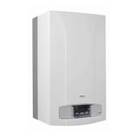
Figure 13a
0307_2201
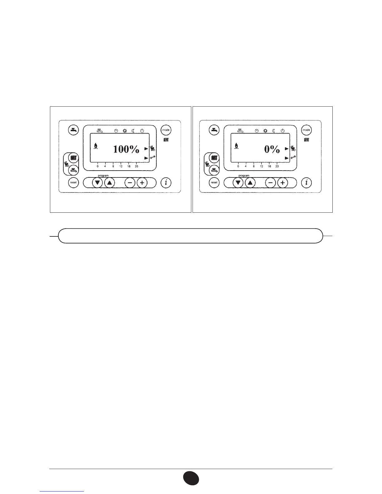
Figure 13b
⇑
⇑
0502_2110

 Loading...