Quick Start Guide
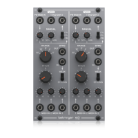
112 DUAL VCO
Legendary Analog Dual VCO
Module for Eurorack
Controls
(1) PW MOD IN – Accepts a voltage from another module to
control the pulse width.
(2) VCO OUT – Send the VCO signal to one or two sources via
3.5 mm TS cables.
(3) WAVEFORM – Select pulse, triangle or sawtooth
waveforms for the VCO.
(4) PULSE WIDTH – Adjusts the pulse width modulation
based on the voltage received at the PW MOD IN jack.
(5) MOD MANUAL – Sets the ratio between the upper and
lower portions of the pulse wave.
(6) SYNC OUT – Sends a synchronization signal via 3.5 mm
TS cable.
(7) RANGE – Sets the pitch range of the VCO in octave steps.
(8) SYNC IN – Accepts a synchronization signal via 3.5 mm
TS cable.
(9) WEAK/STRONG – Determines the accuracy
of synchronization.
(10) PITCH – Fine tunes the pitch.
(11) MOD LEVEL – Adjusts the level of the signal connected
to the associated MOD IN jack.
(12) MOD IN – Accepts voltages that control or modulate
the VCO pitch.
Power Connection
The module comes with the required power cable for connecting
to a standard Eurorack power supply system. Follow these
steps to connect power to the module. It is easier to make
these connections before the module has been mounted into
a rack case.
1. Turn the power supply or rack case power o and
disconnect the power cable.
2. Insert the 16-pin connector on the power cable into the
socket on the power supply or rack case. The connector has
a tab that will align with the gap in the socket, so it cannot
be inserted incorrectly. If the power supply does not have
a keyed socket, be sure to orient pin 1 (-12 V) with the red
stripe on the cable.
3. Insert the 10-pin connector into the socket on the back of
the module. The connector has a tab that will align with the
socket for correct orientation.
4. After both ends of the power cable have been securely
attached, you may mount the module in a case and turn on
the power supply.
(3)
(4)
(1) (2)
(12)
(10)
(11)
(5)
(6)
(7)
(8)
(9)
V 1.0