Quick Start Guide
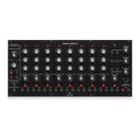
MULTIMODE FILTER /
RESONATOR MODULE 1047
Legendary 2500 Series 12dB State
Variable Filter Module for Eurorack
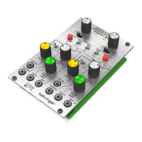
Controls
(1) COARSE – Use this knob to dial in the general frequency
area you want for the high-pass threshold, low-pass
threshold, band-pass center frequency and notch lter
center frequency, then go to the FINE knob to rene the
frequency setting. The frequency set by the COARSE and
FINE knobs (“fc”) will be used simultaneously for every
lter in the module.
(2) FINE – Use this knob to rene and focus the frequency set
by the COARSE FREQUENCY knob.
(3) RESONANCE (NORM/LIM) – This sliding switch lets
you choose between normal resonance mode (NORM)
and limiting mode (LIM), which limits the height of a
lter’s resonant peak. The LIM setting prevents circuit
overload when focusing a lter on a strong harmonic or
fundamental frequency, especially at high Q settings on
the RESONANCE (Q) knob. In other situations, the LIM
setting can result in a very low output signal, and so the
NORM setting is usually preferred.
(4) RESONANCE (Q) – This knob controls the width/
smoothness and narrowness/sharpness of the lter
curves. At low Q settings, the lter curves are wider and
smoother, with a gentler eect on the sound (except for
the notch lter, which functions most eectively at low
Q settings). As you increase the Q setting, the lter curves
gradually become narrower and sharper, which can help
you to focus in on narrow frequency bands. At higher Q
settings, the various lters can produce resonant peaks
in the lter curves that boost some frequencies and may
require moving the RESONANCE (NORM/LIM) switch to
the LIM setting to prevent overloading the circuit (or the
INPUT attenuator knob can be turned down).
(5) F CV 1 – This knob adjusts the strength of the control
voltage signal coming in through the F CV 1 jack.
(6) F CV 2 – This knob adjusts the strength of the control
voltage signal coming in through the F CV 2 jack.
(7) NOTCH FEQUENCY/fc – Use this knob to oset the notch
lter’s center frequency (“fc”) set by the COARSE and FINE
frequency controls. For standard notch lter behavior, the
NOTCH FREQ/fc control should be set to “1” on the scale.
This standard setting can then be tweaked by moving the
NOTCH FREQ/fc knob very slightly around “1”. Also, if
higher Q values are added via the RESONANCE knob while
the notch lter is oset from fc, the higher Q values result
in a resonant peak at fc, with the notch at the point set by
the NOTCH FREQ/fc knob.
(8) INPUT – This knob adjusts the strength of the audio signal
coming through the INPUT jack.
(9) Q CV – This knob adjusts the strength of the Q control
voltage signal coming in through the Q CV jack.
(10) INPUT – Use this jack to route audio signals into the
module via cables with 3.5 mm connectors. You can also
route in a keyboard gate signal to “ring” the lter and
produce a unique percussive sound when you press a key.
(1)
(2)
(3)
(4)
(5)
(6)
(7)
(8)
(9)
(10) (11) (12) (13) (14) (15)
(17)
(16)
Knob Setting Eect
Full CCW
Notch lter output becomes a
copy of the high-pass output
CCW to 1/4
Notch frequency shifts
signicantly below fc
CW to 4
Notch frequency shifts
signicantly above fc
Full CW
Notch lter output becomes a
copy of the low-pass lter output
V 1.0