2
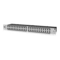
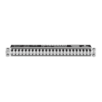
ULTRAPATCH PRO PX3000
1. INTRODUCTION
Thank you very much for expressing your confidence in us by
purchasing the ULTRAPATCH PRO PX3000. The PX3000 is a
multi-functional balanced 48-point patchbay for studio and stage
applications.
What are patchbays for? A patchbay allows you to patch
(or interconnect) the audio signals of most components in your
system from a central point and send them to other units, making
your entire cabling more organized and better suited for
professional work. If you want to use your studio as effectively as
possible, it is recommended that you use a complete patchbay
wiring schemeeven smaller studios will benefit from a less
complex patchbay configuration.
2. PATCHBAY ORGANIZATION
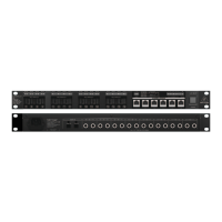
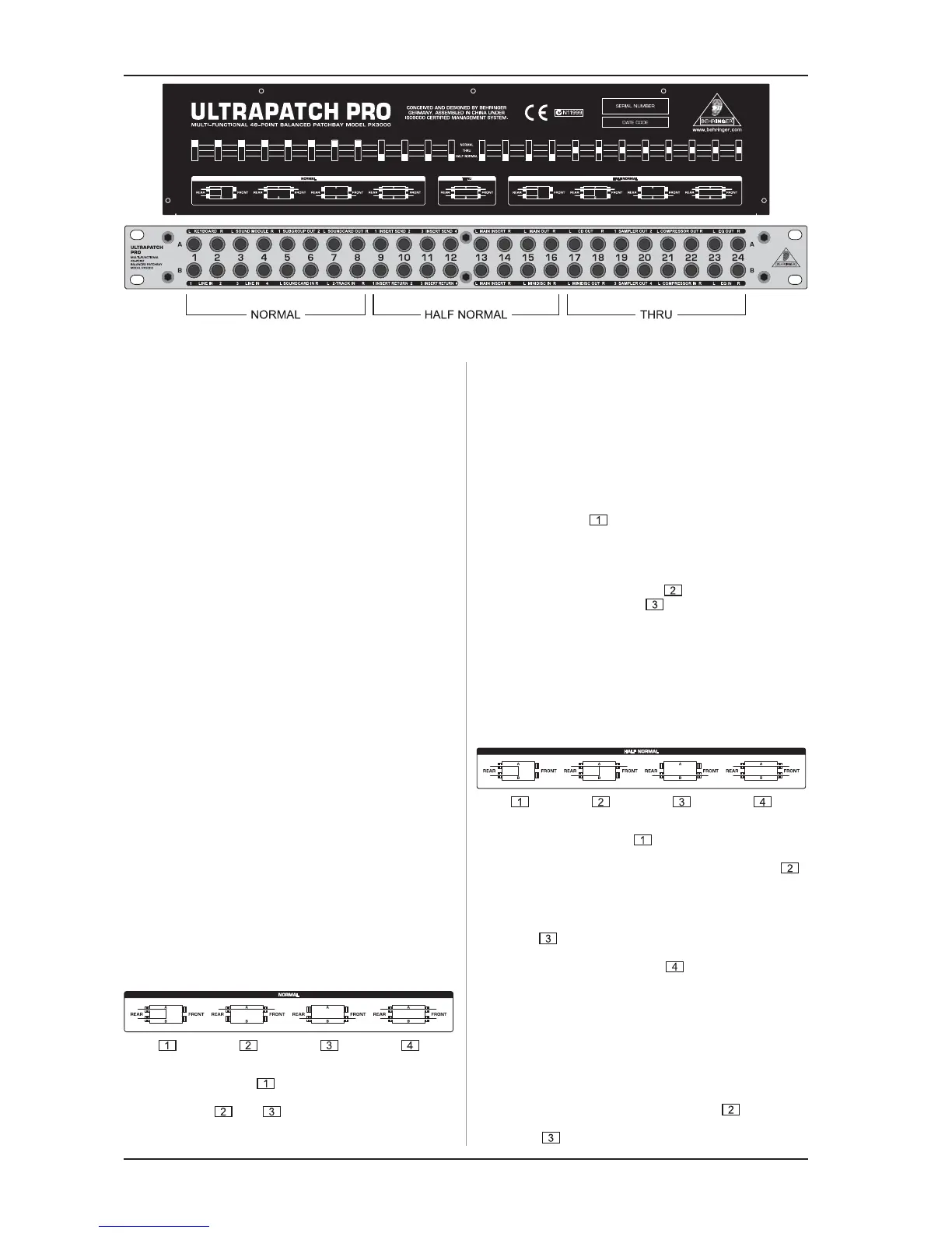
The ULTRAPATCH PRO PX3000 has two rows (A and B) of 24
balanced 1/4" jacks on the 1 HU 19" front rack panel. The same
number and configuration of balanced 1/4" jacks are on the rear
panel. These jacks are grouped in fours (A and B from the front
with the corresponding A and B on the rear) to form the 24
channels. Each channel has a switch on the top of the unit that
allows you to select the operating mode for each channel:
NORMAL (normalized), HALF NORMAL (half normalized) and
THRU (through-connected). Connect your audio equipment to
the rear jacks, then you can easily interconnect your equipment
or reconfigure your setup using short patch cables plugged into
the jacks on the front panel. Of course, you can also use
unbalanced cables.
+ Basic rule: on a patchbay the upper jacks are always
outputs, the lower jacks inputs.
When using several patchbays, plan the layout of your standard
configuration to avoid a tangle of cables. Arrange the channels
one below the other in such a way that you could connect several
patchbays without having to cross connect or span great
distances.
2.1 NORMAL mode
In NORMAL mode the rear A & B jacks of the channel are
connected together (pos. ). The connection between the rear
jacks is disabled when you insert a cable into jack A or B on the
front panel (pos. and ).
In the example above, top-row channels 1 to 4 are from the
outputs of a keyboard and a MIDI sound module. They are
connected, in this example configuration, to input channels 1 to 4
on the mixer.
Channels 5 and 6 are from the subgroup outputs of a mixer and
are connected, in this example configuration, to the inputs of a
computer audio card. Audio sequencer software records the music
signals directly onto the hard disk of the computer. Channels 7
and 8 connect the soundcard outputs to the 2-track inputs of the
mixer. Since the rear-panel jacks are connected together in the
NORMAL mode (pos. ), the subgroup signals can be recorded
directly onto the PC and played back via the 2-track input of the
mixer (playback/monitoring), without a single patch cable having
to be plugged in! In this way, you can build up a basic configuration
for your studio, which can be easily modified by simply patching
signals via the front-panel jacks (pos. ) or by feeding in external
signals via patch cables (pos. ). You could, for example,
connect the keyboard signal to channels 3 and 4 by patching 1A
to 3B, and 2A to 4B. So, before wiring your studio, it is advisable
to identify the connections that will be used most frequently and
set them up, as your basic configuration, one above the other on
the patchbay. Then you will have a clear overview of all
connections and still be flexible.
2.2 HALF NORMAL mode
In HALF NORMAL mode, the rear A & B jacks of the channel
are connected together (pos. ). Unlike NORMAL mode, the
connection between the rear-panel jacks is not disabled when a
1/4" plug is inserted into jack A on the front panel (pos. ).
This allows you to take the signal from a mixers channel strip in
parallelwithout interrupting the signal path on the channel strip.
Like NORMAL mode, the connection between the rear-panel jacks
is disabled when a 1/4" plug is inserted into jack B on the front
panel (pos. ). When 1/4" plugs are inserted into both jacks A
& B on the front panel, the front jacks will be connected separately
to the corresponding rear jacks (pos. ). This is called an input
break and is used mainly to insert an effect or processor into the
signal path.
In the example above, top-row channels 9 to 14 are the sends
(tip contact of insert points) from mixer channels 1 to 4 plus the
main left & right sends. They are connected, in this example
configuration, to their respective returns (ring contacts of insert
points) of the mixer.
Outputs from the mixer sends can be taken from jack A without
disabling the connection to the returns (pos. ). The mixer
returns can be used as external line inputs, by patching cables to
jack B (pos. ). External effects or processors can be inserted
2. PATCHBAY ORGANIZATION
 Loading...