Technical Data
1405
Power Supply 24 VAC, ±20%, 50/60 Hz, 24 VDC, ±10%
Power Consumption Running 2.5 W
Power Consumption Holding 1 W
Transformer Sizing 5 VA (class 2 power source)
Shaft Diameter 3/8” to 1/2” round, centers on 1/2”
Electrical Connection 3ft [1m], 18 GA plenum cable with 1/2”
conduit connector
Overload Protection electronic throughout 0° to 95° rotation
Electrical Protection actuators are double insulated
Operating Range Y 2 to 10 VDC, 4 to 20 mA w/ ZG-R01 (500 Ω,
1/4 W resistor)
Input Impedance 100 k Ω for 2 to 10 VDC (0.1 mA), 500 Ω for
4 to 20 mA
Feedback Output U 2 to 10 VDC (max 0.7 mA) for 95°
Angle of Rotation Max. 95°,
Torque motor Min. 35 in-lbs [4 Nm]
Direction of Rotation (Motor) reversible with built-in switch
Direction of Rotation (Fail-Safe) reversible with CW/CCW mounting
Position Indication visual indicator, 0° to 95° (0° is full spring
return position)
Running Time (Motor) 150 sec
Running Time (Fail-Safe) <25 sec @ -4°F to 122°F [-20°C to 50°C],
<60 sec @ -22°F [-30°C]
Ambient Humidity max. 95% RH non-condensing
Ambient Temperature Range -22°F to 122°F [-30°C to 50°C]
Storage Temperature Range -40°F to 176°F [-40°C to 80°C]
Housing NEMA 2, IP54
Housing Material zinc coated steel
Agency Listings† cULus acc. To UL 873 and CAN/CSA C22.2
No. 24-93
Noise Level (Motor) <30 dB (A)
Noise Level (Fail-Safe) <62 dB (A)
Servicing maintenance free
Quality Standard ISO 9001
Weight 3.1 lb [1.4 kg]
†Rated Impulse Voltage 800V, Type of action 1.AA, Control Pollution Degree 3
Torque min. 35 in-lb, for control of air dampers.
Application
For fail-safe, modulating control of dampers in HVAC systems. Actuator sizing
should be done in accordance with the damper manufacturer’s specifications.
The actuator is mounted directly to a damper shaft from 3/8” up to 1/2” in
diameter by means of its universal clamp, 1/2” shaft centered at delivery.
For shafts up to 3/4” use K6-1 accessory. A crank arm and several mounting
brackets are available for applications where the actuator cannot be direct
coupled to the damper shaft. The actuator operates in response to a 2 to 10
VDC, or with the addition of a 500Ω resistor, a 4 to 20 mA control input from an
electronic controller or positioner. A 2 to 10 VDC feedback signal is provided for
position indication.
Operation
The LF series actuators provide true spring return operation for reliable
fail-safe application and positive close-off on air tight dampers. The spring
return system provides consistent torque to the damper with, and without,
power applied to the actuator. The LF series provides 95° of rotation and is
provided with a graduated position indicator showing 0 to 95°. The LF24-SR
US uses a brushless DC motor which is controlled by an Application Specific
Integrated Circuit (ASIC) and a microprocessor. The microprocessor provides
the intelligence to the ASIC to provide a constant rotation rate and to know
the actuator’s exact fail-safe position. The ASIC monitors and controls the
brushless DC motor’s rotation and provides a digital rotation sensing function to
prevent damage to the actuator in a stall condition. The actuator may be stalled
anywhere in its normal rotation without the need of mechanical end switches.
Power consumption is reduced in holding mode.
Dimensions (Inches[mm])
2.74" [
69.6]
2.25" [
57.1]
0.73"
[
18.54]
3.23" [
0.25"
[
6.25]
1.15"
[
29.3]
2.3" [
58.42]
3.15" [
80]
7.66
" [
194.501]
0.2" [
5.08]
0.98
" [
25] 4.72
" [
120] 0.39
" [
10]
0.97" [
24.6]
3.86" [
98]
1.69
" [
43] 3.66
" [
93]
6.1
" [
155]
3.66
" [
93]
6.1
" [
155]
0.26
" [
6.5]
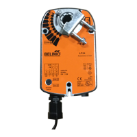
LF24-SR US - Damper Actuator
Modulating, Spring Return, 24 VAC/DC, for 2 to 10 VDC or 4 to 20 mA Control Signal
800-543-9038 USA 866-805-7089 CANADA 203-791-8396 LATIN AMERICA / CARIBBEAN
Date created, 11/29/2017 - Subject to change. © Belimo Aircontrols (USA), Inc.