INSTRUCTIONMANUAL
Bx4
IF YOUSHOULD EXPERIENCE A PROBLEM
WITH YOUR BLACK & DECKER PURCHASE,
CALL 1-800-54-HOW-TO (1-800-544-6986).
IN MOST CASES, A BLACK & DECKER REPRESENTATWE-
CAN RESOLVE YOUR PROBLEM OVER THE PHONE-
IF YOU HAVE A SUGGESTION OR COMMENT,-
GIVE US A CALL. YOUR FEEDBACK IS VITAL
TO THE SUCCESS OF BLACK & DECKER'S QUALITY -
IMPROVEMENT PROGRAM.
\
R =
i
A F
SAVE THIS MANUAL FOR FUTURE REFERENCE.
VEA ELESPANOLEN LA CONTRAPORTADA.
INSTRUCTIVODEOPERACIC)N,CENTROSDESERVIClOY PC)LIZADEGARANTJA.
ADVERIENCIA:LEASEESTEINSTRUCTIVOANTESDEUSARELPRODUCTO.
CATALOG NO. WM125 FORM NO. 607269-01 PRINTED IN CHINA APR. '03
IMPORTANT SAFETY INSTRUCTIONS
PLEASEREAD AND UNDERSTAND ALL INSTRUCTIONS CAREFULLY
BEFOREUSING THE UNIT.
1. Do not load with more than 350pounds. (160 kg)
2. Do not apply an unbalancedIoadwhich could causetheWork Centerto
tip over.
3. Do not usethe Work Centeras a stepladderor standingplatform.
Do not usethe lower crossBraceas a step.Thecrossbrace is a foot REST
only.
4. Do not storework centeroutdoors or in a clamp location.
5. Avoid appyling excessivebrce whenclam ing with the swivelpg.es
6. Be surethat the legsare fully open, locke[in position and securedvia the
locking knobs.
7. When using a powertool with theWork Center,follow the safely
instructionsin the tools instructionmanual.
8. Always wear safelyglasseswhen operating power tools.
9. Never mountpower toolsdirectly in vise jaws; pressuremay damagetools.
10. An even pressureof thevise jaws on theworkpiece is essential.
TightenBothcrank handles uniformly.
11. Supportoverhanging loadsto preventtipping. __
) ° Tx2
®
I
I
6mm;lo:°_°:ol;
114" % o 100ram / 4"
t .o o Oo:O_
ASSEMBLY INSTRUCTIONS
NOTE: For assembly of the WM125 Workmate ®you will need a
hammer, flat bladed screwdriver and the provided nut driver part (U).
Follow the sequence shown in the diagrams and described in the
steps Below.
STEP1:
Empty the contents of the box and identify all components.
STEP2:
Empty the contents of the parts pack and identify all components.
STEP3:
Guide carriage bolt D through slot in vise bracket of assembly S,
spacer {F)outer leg (T) and secure with knob (E). Repeat this step using
assembly (R).
STEP4:
Place the rear step board (Z) over the legs, align holes and secure with
Pan Head bolt, M6 x 30ram (C) and M6 nut (A). Use flat bladed
screwdriver and nut driver (U) to secure.
STEP5:
Place the front step board (Y) over th.elegs, align holes and secure with
Pan Head bolt, M6 x 30ram (C) and M6 nut (A). Use flat bladed
screwdriver and nut driver (U) to secure.
STEP6:
Thread pivot nut (M) about 1/4 of the way onto vise screw (N) and
insert rod end through front hole of leq assembly (S). Repeat with other
pivot nut and vise screw using front hole of leg assembly (R).
STEP7:
Place front slide blocks H onto the leg assemblies S and R as shown.
Place vise aw X, V-groove facing towards clamp edge, over the two
slide blocks (H). Insert two self-threading hex head bolts (B), through the
recessed holes in the aw and tighten securely with nut driver (U). Place
the two rear slide blocks (J) over pivot nuts (M) as shown. Place the rear
vise aw (W), V-groove facing towards clamp edge, over the slide
blocks J). Insert two self-threading hex head bolts (B), through the
recessed hoes in the jaw and tigJ_tensecure y with nut driver (U).
STEPB:
Push the Snap-in Knobs (L)into the handle arms (K) as shown.
STEP9:
Place handle arm (K) over the vise screw rod end (N), align holes and
secure the rollpin (G) using a hammer.
STEP10:
Install the rubber feet (P)to bottom of legs as shown. Note correct
orientation of feet.
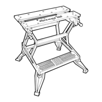
CLOSING AND STORAGE
1. Loosenboth locking knobs.(Step11)
2. While holding thejaws asshown,tilt theWork Centertowardsyou
while lifting up on thefront jaw. TheWork Centerwill begin to swing
closed.
Z_ WARNING: DO NOT PLACEFINGERSNEAR WORK CENTER
LEGSWHEN CLOSING - PINCH HAZARD.
3. Close the unit fully as shown in Step 11. Tighten both locking knobs.
TheWork Center is now storable in a convenient minimum space.
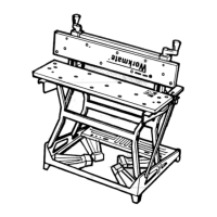
HOLDING IRREGULAR SHAPES WITH WORKMATE CENTER
Using the swivel peqs in the appropriate holes and the independent
action of both vise _andles, the Work Center can secure the most
irreqular shapes. It Jetsyou grip objects that used to be impossible to
holc[ Rotate swivel pegs to accept irregular shapes. Outside swivel pegs
extend capacity for the diagonal grip with jaws fully open. (Step 12 & 13)
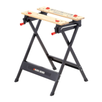
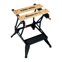
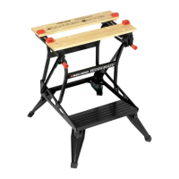
WORKING WITH YOUR WORKMATE WORK CENTER
The Work Center is a vise and workbench all in one. Its basic design
and special features help you perform a complete range of workshop
tasks kom the simplest to the most complicated. The heart of the
Work Center is in the action of the two parallel vise jaws, The two vise
handles adjust the jaws to a maximum of 4 1/2 (114ram) jaw
openinq. Because each handle works independently, the opening can Be
taperec[from 0 to 5 (127mm) maximum. Use of the swivel pegs in the
appropr!a!e vise holes extends the vise capacity of the Work Center up
to 10-3/4 (273mm) parallel clamping and 22-1/2 (570ram) when
objects are held diagonally. The Work Center is a useful sawhorse and
holds material securely. Sawinq tubular pieces is easy when they are
held horizontally in the specialty desiqned V grooves running along
the face of the vise jaws. Black & Decker supplies,,,at,extra cost, clamps
for securing larger projects to the Workmate an,d, _ clamps are
available at your local hardware store. Vertical V grooves in the vise
jaws permit rigid vertical grasping of tubular objects.
NOTE: Place your foot on the foot board of the Work Center to steady it.
DO NOT USE AS A STEP.
ACCESSORIES
Recommended accessoriesfor use with your Work Center are available at
extra cost from your local dealer or autl_orized service center. Please
consult your Yellow Pages for a service center nearest you under Tools
Electric. If you need assistance in locating any accessory for your Work
Center, please contact Black & Decker.
Service Information
Black & Decker offers a full network of company-owned and authorized
service locations throughout North America. All Black & Decker Service
Centersare staffed with trained personnel to provide customers with
efficient and reliable power tool service. Whether you need technical
advice repair, or genuine factory replacement parts contact the
Black & Decker location nearestyou. To !!nd your local service location
refer to the ye ow page directory under Toos--E ectric or ca :
1-800-54-HOW-TO.
Full Two-Year Home Use Warranty
Black & Decker (U.S.) Inc.warrants this product for two years against any
defectsin material or workmanship. The defective product will k;e replaced
or repaired at no charge in either of two ways:
The first which will result in exchanges only isto return the product to the
retailer from whom it was purchasec] provided that the store is a
participating retailer). Returnsshould be made within the time period of
the retailer spolicy for exchanges(usually 30 to 90 day,safter the sale).
Proof of purchase may be required. Pleasecheckwith the retailer for their
specific return policy regarding returns that are beyond the time setfor
exchanges.
The secondoiqtionisto take or send theproduct (prepaid) to a Black &
Decker owned or authorized Service Center for repair or replacementat our
option. Proof of purchase may be required.,Black & Deckerowned and
authorized servicecentersare listed under Tools-Electric in theyellow
pagesof the phonedirectory. Thiswarranty doesnot apply to accessories.
Thiswarranty gives you specificlegal rights and you may have other ri]hts
which vary from stateto state. Shouldyou have any questions contact the
manager of your nearest Back & DecJ<erService Center.
This product is not intended for commercial use.
Imported by
Black & Decker (U.S.) Inc.,
701 E. Joppa Rd.
Towson, MD 21286 U.S.A.
See 'Tools-Electric' I-_
- Yellow Pages -
for Service & Sales