Quick Start Guide
B9512G/B8512G Control Panel
Need more help?
For detailed instructions, refer to the control panels Installation
and System Reference Guide (ISRG) chapter number (ISRG #5.2)
included on the CD provided with the control panel.
1 = PC direct, connect using AutoIP (WiFi off , wait 2 minutes)
2 = PC direct, connect using Male A to Male A USB (B99)
3 = “E” variants do not include on-board Ethernet
SDI2 Specifi cations
Unshielded, 4 conductor, 22–12 gauge cable
Maximum cable length 1000 ft. single run, 7500 ft. system total
Allows a combination of home run, daisy chain and T-tapping wiring confi gurations
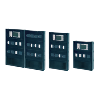
Control Panel Mounting
Enclosure Models B8103/D8103/D8108A/D8109
Back of
control panel
Removable Terminal Strips
Optional Devices Overview
Max. # of devices
Device Type Model Description ISRG # B9512G B8512G Address Notes
Keypad B91x/B92x 2-line Basic 9.1.1 32* 16* 01–32 Similar device types
must use diff erent
addresses.
Diff erent device types
may use the same
address.
*Maximum number of
total system keypads
(including 16 SDI
keypads.)
B925F/B926F 2-line Fire 9.1.4–9.1.5 32* 16* 01–32
B930 5-line, ATM LCD 9.1.6 32* 16* 01–32
B942/B942W Touch Screen 9.1.7 32* 16* 01–32
D1255/D1255RB Vacuum Fluorescent
Keypad (RB=Fire)
9.1.8 16 16 01–16
D1260x ATM LCD Keypad 9.1.8 8 8 01–08
I/O Expander
B208 8-input 13.1 59 9 01–59
B308 8-output 11.1 59 9 01–59
B299 POPEX 13.2 6 1 1–6
B600 ZONEX 11.2, 13.3 1 1 N/A
RF Receiver
B810 Bosch RADION 14.1 1 1 1
B820 Inovonics 14.2 1 1 1
Door Control
B901 Access Control Interface
Power Supply
B520 12V DC, 2A 6.3 4 2 01–04
Remote Cellular
B450 B44x Plug-in Interface 8.4 1 1 1
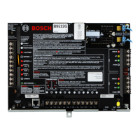
On-board Inputs and Outputs
Terminal Description Specifi cation
1 2
Transformer Class 2 16.5 VAC 40 VA 60Hz
9
COMMON Negative, 12V DC Aux Power
10
Earth Ground Cold water pipe, or similar
54
Battery 12 VDC up to 38 Ah
6 7 8
Programmable
power outputs
12 VDC nominal
3
Aux Power 12 VDC, 1.4 A
SDI2 SDIx
SDI2 Bus Modules and keypads, use
terminal or interconnect wiring
POINT 1 POINT 8
Alarm Inputs 1k Ω EOL
TMPR
Tamper Optional tamper switch
ZONEX
Legacy zone
expansion
12 VDC nominal
RESET
Reset Button Hold 5 seconds to enter or
exit service mode
Heartbeat Slow = normal,
Rapid = service mode
MOD-1 MOD-2
Plug-in Communication module
options
Technology Location ISRG #
Reporting
Personal Notifi cations
Remote RPS Programming
Local RPS Programming
Remote Security App
Ethernet
3
On-board 7.5
Cellular B44x
Plug-in
8.2
Telephone B430
Plug-in
7
USB On-board 3.3.8
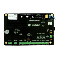
Communication Devices
1
2
Transformer
AUX Power
Battery
Outputs A, B, C
Common
Earth Ground
USB
Power
Status
Ethernet
USB
On-board Points 1–8
ZONEX
Tamper
Reset Button
SDI2
SDI/SDI2
Plug-in module
connections
Heartbeat LED