D7024 | Operation and Installation Guide | 7.0 Control Panel Programming
48 Bosch | 7/05 | 31499J
2. Enter the relay you want to assign and press [#].
The display reads:
3. Enter the output number, 00 to 63, you want to map
to Zone A and press [#].
A similar display for Zone B appears.
4. When all four zones are assigned, the preceding
window appears.
Multiplex Relays
Shortcut:
0-PROG > 5-PROG OUTPUTS > 2-RELAYS
The display scrolls through the relay options.
1. Press [4] for MULTIPLEX and access:
2. Enter the number corresponding with the output
you want programmed and press [#].
To determine the output number of a multiplex
relay, note that multiplex relays are the second
point of an I/O module. Adding 1 to the address of
the I/O module gives the relay module address.
When the relay is selected, the display prompts you
to enter four zones to activate this output.
3. Enter the first zone, 00 to 63, you want to map to
drive this output and press [#].
A similar display for Zone B, C, and D appears
allowing up to four zones to drive this input. When
all four zones are assigned, the preceding window
appears.
7.6 PROG Accounts
7.6.1 Phone Numbers
Shortcut:
0-PROG > 6-PROG ACC'NTS > 1-PHONE NUMS
The system can be programmed with two reporting
telephone numbers. Phone #1 is used with Account
Number 1 and Phone #2 is used with Account Number
2. Remote programming occurs on Phone Line 1 using
Phone #3.
PHONE #1: Phone Number 1
PHONE #2: Phone Number 2
COMPTR PHONE: Sets the number to call for remote
programming.
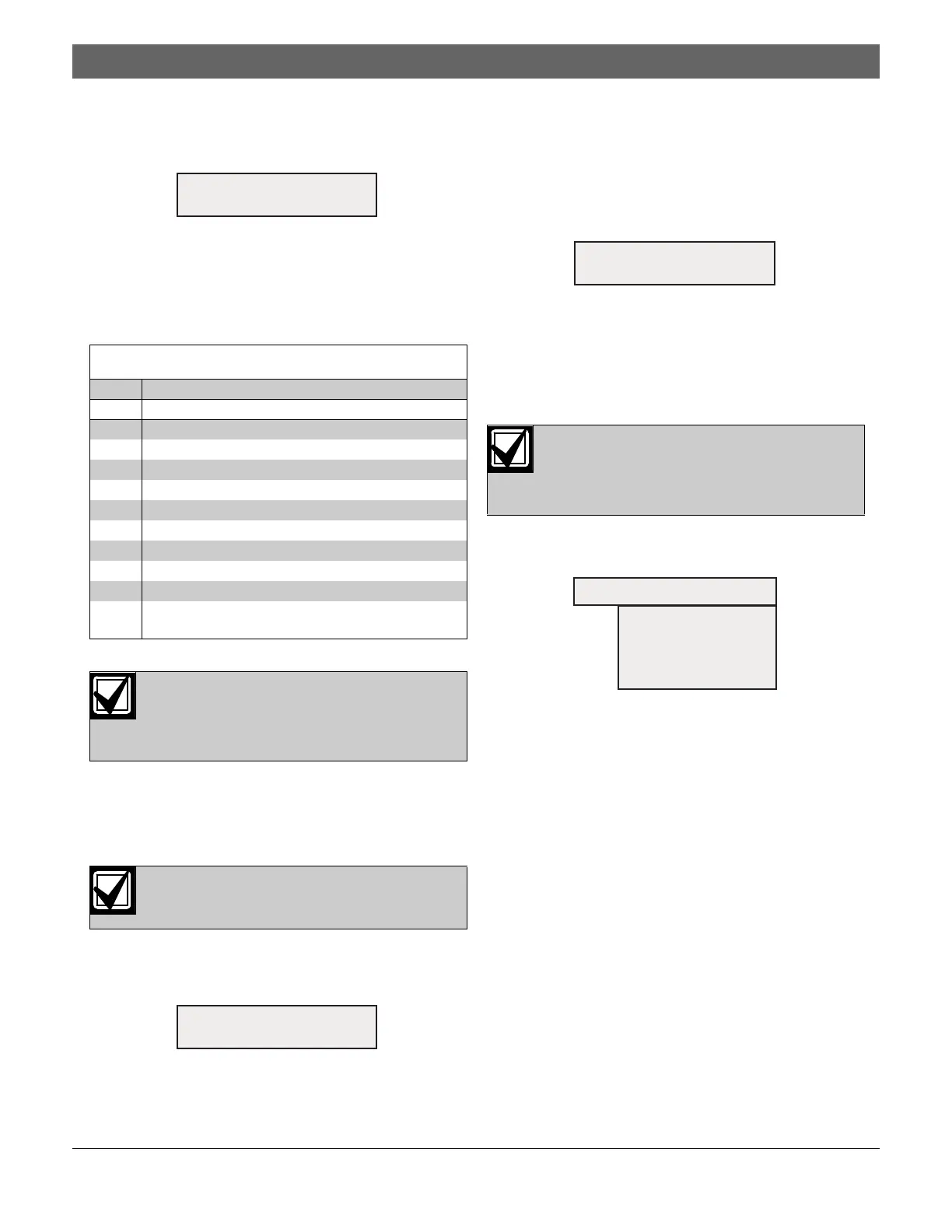
Table 25: Pre-Assigned Zone Quick Reference
Zone Pre-Assigned Condition
52 General Fire Alarm (non-silencing)
53 General Fire Alarm (silencing)
54 Ground Start
57 Communication Trouble
58 General Supervisory Alarm (non-silencing)
59 Alarm Verification
60 AC Failed
61 General Waterflow Alarm (non-silencing)
62 General Trouble
63 General Fire Alarm, Monitor, Waterflow supervisory
(non-silencing)
An output point cannot be assigned to more
than four zones. It is not necessary to map
each output to four zones. Each zone can
have several outputs mapped to it.
Do not use this menu to program addresses
configured as inputs.
OUTPUT ZONE A (XX)
(00-63):
MUX OUTPUT
(009-255):
An output point cannot be assigned to more
than four zones. It is not necessary to map
each output to four zones. Each zone can
have several outputs mapped to it.
OUTPUT ZONE A (XX)
(00-63):
PROG ACCNTS
1- PHONE NUMS
2- PHON CONTROL
3- RPT STEERING
4- RING COUNT
5- COMM. TRIES
6- MACH. BYPASS

 Loading...


